Vers. No. 6.1
80 Released: 25/04/2017
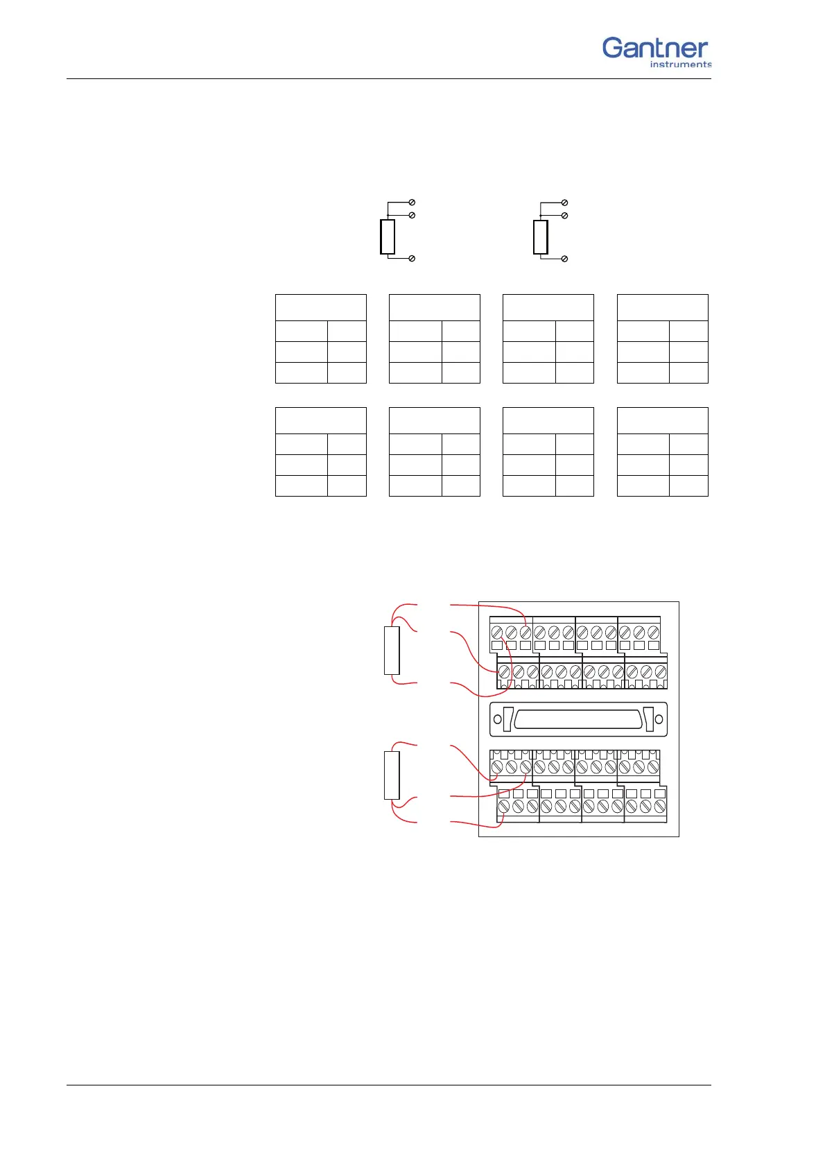
4 Connecting the modules → Q.bloxx A116: Connecting sensors
The bridge excitation voltage is 2 V
DC
; with 350 sensor resis-
tance you can also use 4 V
DC
.
Fig. 4-74 A116, measurement with a strain-gauge quarter bridge,
direct connection.
Fig. 4-75 A116, measurement with a strain-gauge quarter bridge.
Connection assignment for the Q.bloxx Connection Termi-
nal CT A116.
You will find the terminal assignment for the Cable A116 in the
first section of this chapter. With quarter bridges only U
EXC+
,
U
EXC–
and U
SIG+
are assigned. For the activation of the shunt
resistance refer to Section 4.18.3.
350 Ω
U
Sig+
U
Exc–
U
Exc+
U
Sig+
U
Exc–
Input 1
U
Exc+
A3
U
Exc–
A4
U
Sig+
B3
Input 2
U
Exc+
A7
U
Exc–
A8
U
Sig+
B8
Input 3
U
Exc+
A11
U
Exc–
A12
U
Sig+
B11
Input 4
U
Exc+
A15
U
Exc–
A16
U
Sig+
B15
Input 5
U
Exc+
A19
U
Exc–
A20
U
Sig+
B19
Input 6
U
Exc+
A23
U
Exc–
A24
U
Sig+
B23
Input 7
U
Exc+
A27
U
Exc–
A28
U
Sig+
B27
Input 8
U
Exc+
A31
U
Exc–
A32
U
Sig+
B31
U
SIG+
U
EXC+
Strain gauge
2
Q.bloxx 116 Junction Box
2
1357
468
U
EXC-
U
EXC+
U
SIG+
Strain gauge
1
SG
3
SG
5
SG
7
SG
4
SG
6
SG
8
U
EXC-

 Loading...