EasyManuals Logo

Gantner Q Series User Manual

Gantner Q Series
150 pages
To Next Page IconTo Next Page
To Previous Page IconTo Previous Page
Page #74 background imageLoading...
Page #74 background image
Vers. No. 6.1
74 Released: 25/04/2017
4 Connecting the modules Q.bloxx A111: Connecting sensors and I/O
IMPORTANT
Voltages which exceed the admissible limits produce incorrect
measurement data, because the inputs are protected against
overvoltages and limit the input voltage.
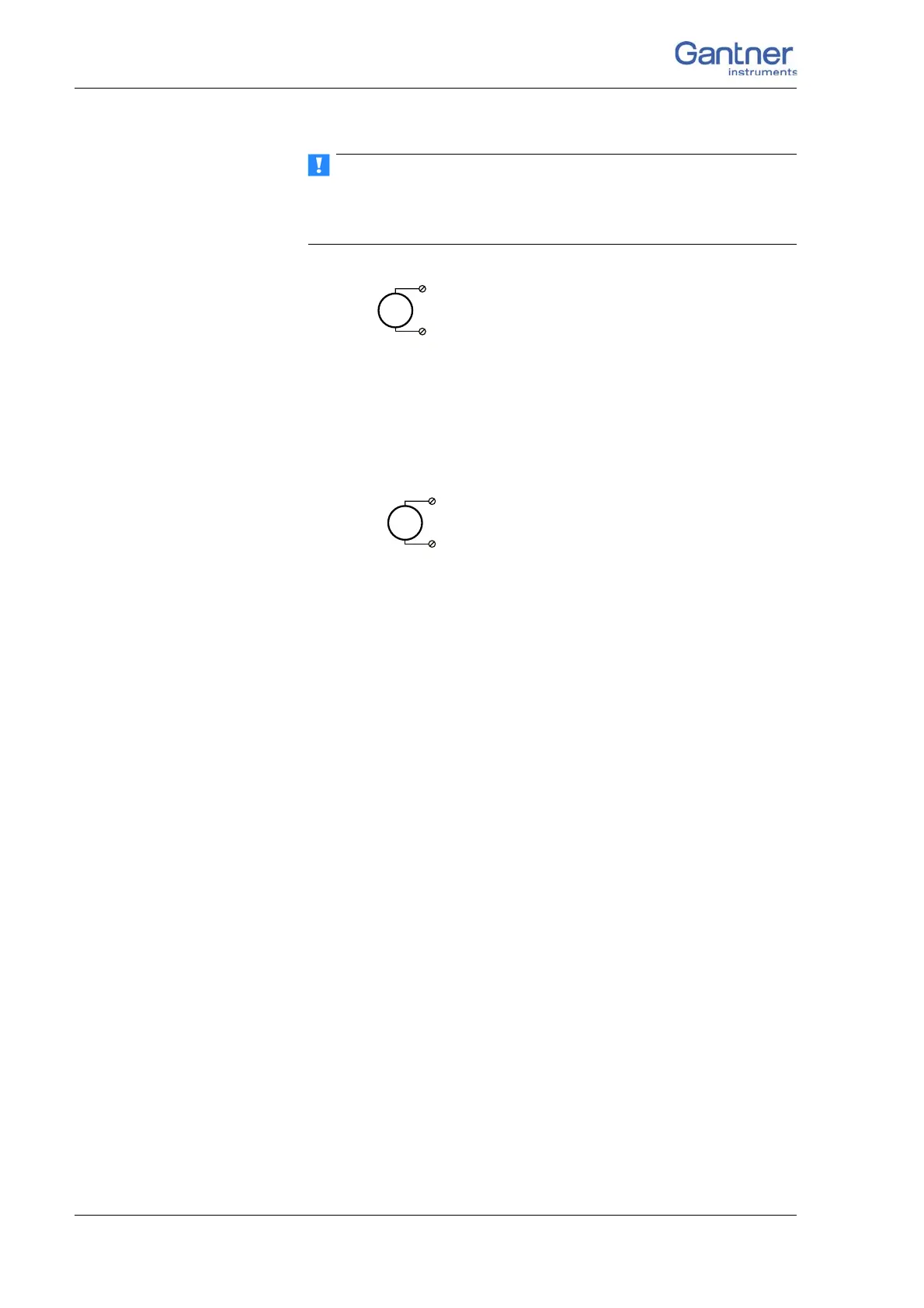
Fig. 4-68 A111, measurement of voltage.
4.17.2 IEPE/ICP
®
Sensor
The sensor is supplied with 4 mA of current from the module (cur-
rent supply).
Fig. 4-69 A111, measurement with IEPE or ICP
®
sensors.
U
2, 7 (+)
4, 9 (–)
IEPE
4, 9 (–)
2, 7 (+)

Table of Contents

Questions and Answers:

Question and Answer IconNeed help?

Do you have a question about the Gantner Q Series and is the answer not in the manual?

Gantner Q Series Specifications

General IconGeneral
BrandGantner
ModelQ Series
CategoryControl Unit
LanguageEnglish

Related product manuals