Vers. No. 6.1
26 Released: 25/04/2017
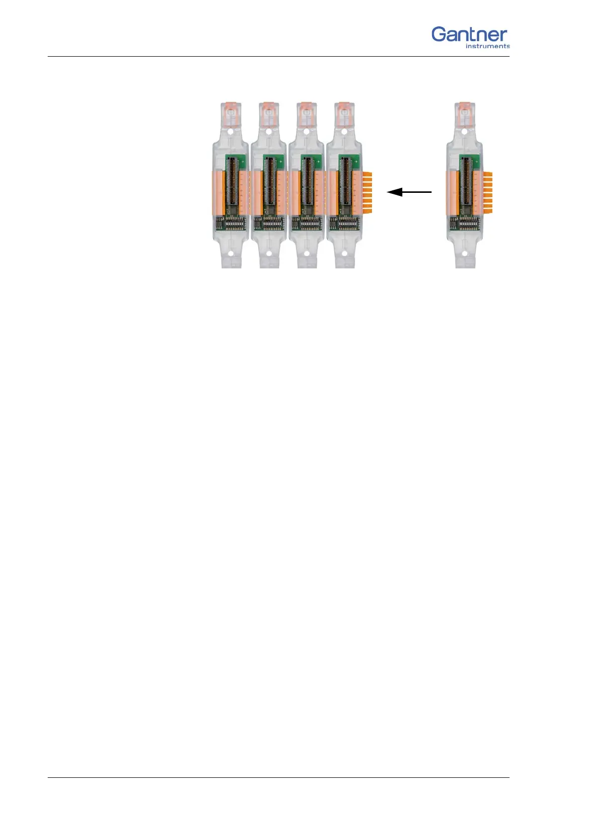
4 Connecting the modules → Connecting the base
Fig. 4-3 Connecting several bases.
To remove, insert a narrow screwdriver into the hole at the lower
end, press the screwdriver upwards on the handle to push the
metal clip in the latching cam downwards and from below pull
the base from the mounting rail to the front.
4.1.5 Q.bloxx Extension Socket QES
If you want to connect more than 16 modules, need a further feed
for the supply voltage or want to spread modules over two bus
interfaces, you need the Q.bloxx Extension Socket QES; modules
inserted into the sockets only use the lines of UART 1. Since a
maximum of 16 modules per bus interface is possible, with more
modules yo
u have to use UART 1 and UART 2.
Wi
th the extension socket you can additionally connect the mod-
ules arranged to the right of the socket to the lines of UART 2, i.e.
the module cro
sses the lines of the two UARTs: The lines from
UART 1 on the left side then go to the lines of UART 2 on the
right side wh
ere they remain unused. The lines from UART 2 on
the lef
t side go to the lines of UART 1 on the right side and are
used by the modul
es. Both UART interfaces are accessible via the
extension socket and via the plug on the socket on the far left.
➡ All modules to the right of the extension socket can only be con-
nected to the power supply via the plug in the extension socket,
since
there is no connection to the modules on the left side. All
modules to the left of the extension socket must be supplied via
the socket on the far left.
Using less than 16 modules
In this way you can use the Q.bloxx Extension Socket QES to

 Loading...