Q.series
Gantner Instruments GmbH
107
5 Configuration → Configuring analog inputs
able number Vx) to mark it. Using the context menu, you can then
cut, paste and copy the variable, overwrite it with a copied vari-
able or delete it.
5.3 Configuring analog inputs
5.3.1 Setting sensor parameters
In order to set parameters you should be connected to the mod-
ule and have called the configuration program (ICP 100 which is
started automatic
ally by test.commander):
Mark a module and
select Configuration fr
om the context menu or double click on a
module or module signal (variable) to start the configuration pro-
gram. Then carry out all the module settings in the window of this
program.
You can however also configure a proje
ct without a direct con-
nection and then, once you have establ
ished the connection, load
the corresponding files into the modules and load Test Controller.
All module signals are defined as variabl
es. Therefore, for the
entry activate the tab Variable definition in the configuration
program.
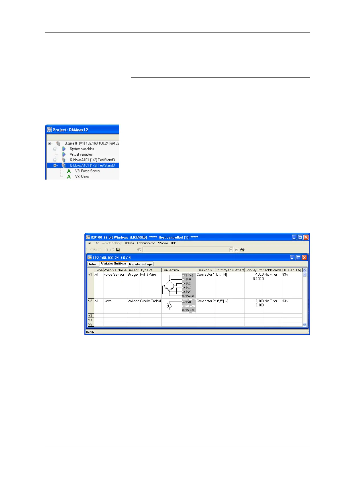
Fig. 5-1 Dialog with the configuration for force transducers (6-
wire) and voltage input.
Procedure 1. Click in the column Type of the first row (V1 = Variable 1) or
mark the row (click on V1) and use Variable definition >
Type.
2. Select Analog. Input.
3.
Click in the column Variable name and allocate
a name iden-
tifying the signal from the connected sensor.
4. Click in the column Sensor and specif
y the type of sensor.

 Loading...