Vers. No. 6.1
46 Released: 25/04/2017
4 Connecting the modules → Q.bloxx A101: Connecting sensors and I/O
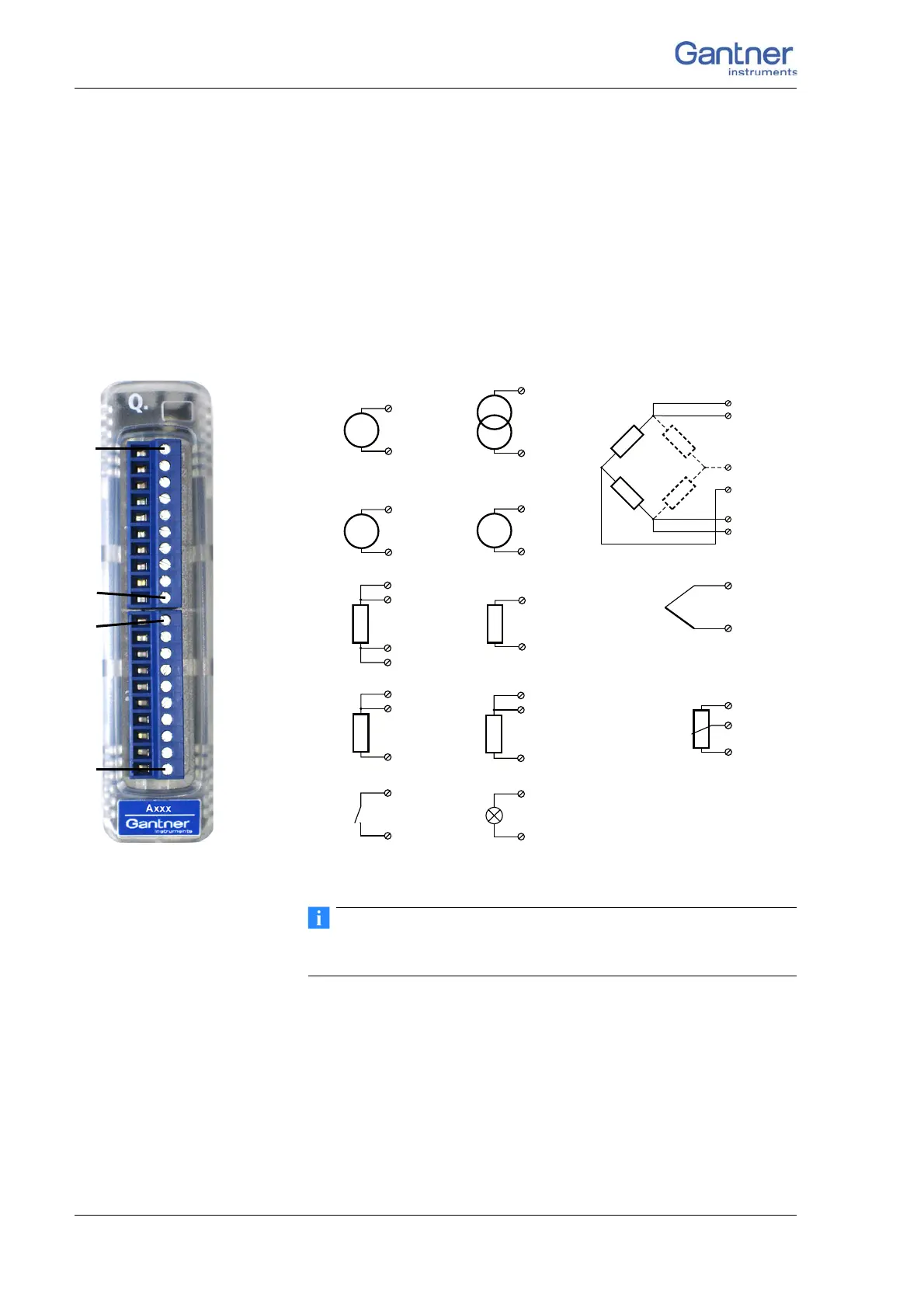
4.8 Q.bloxx A101: Connecting sensors and I/O
The Q.bloxx Module A101 has two electrically isolated analog
inputs and two digital inputs or outputs. The pin assignment of
the two connector strips is identical and the connection terminals
have numbers for identifying the connections.
GND identifies the measurement ground of an input, 0 V and +V
refe
r to the (external) supply voltage connections. Measurement
ground and (module) supply voltage are electrically isolated in
the module.
Fig. 4-18 Pin assignment for Q.bloxx Module A101.
Further information on transducers and sensors can also be
found in Chapter 6 ff. page 135.
4.8.1 Voltage
With voltage measurements two connection variants are possible,
depending on the level of the voltages to be measured: up to 10 V
and up to 60 V.
4
(5)
2 (+)
3
7 (GND)
6
10110 1Plug 1Plug 2
up to 10 V
up to 60 V
3 (+)
7 (GND)
I
3 (+)
7 (GND)
2
3
4
2
3
4 (–)
3 (+)
IEPE
D
in
D
out
10
+V
0V
10
2
5
3
4
160 V
2UF
3A
In
1
4A
In
2
5A
In
3
6A
In
4
7GND
8IEPE
9TEDS
10 DIO
160 V
2UF
3A
In
1
4A
In
2
5A
In
3
6A
In
4
7GND
8IEPE
9TEDS
10 DIO
requires Q.bloxx
Terminal CJC

 Loading...