Vers. No. 6.1
72 Released: 25/04/2017
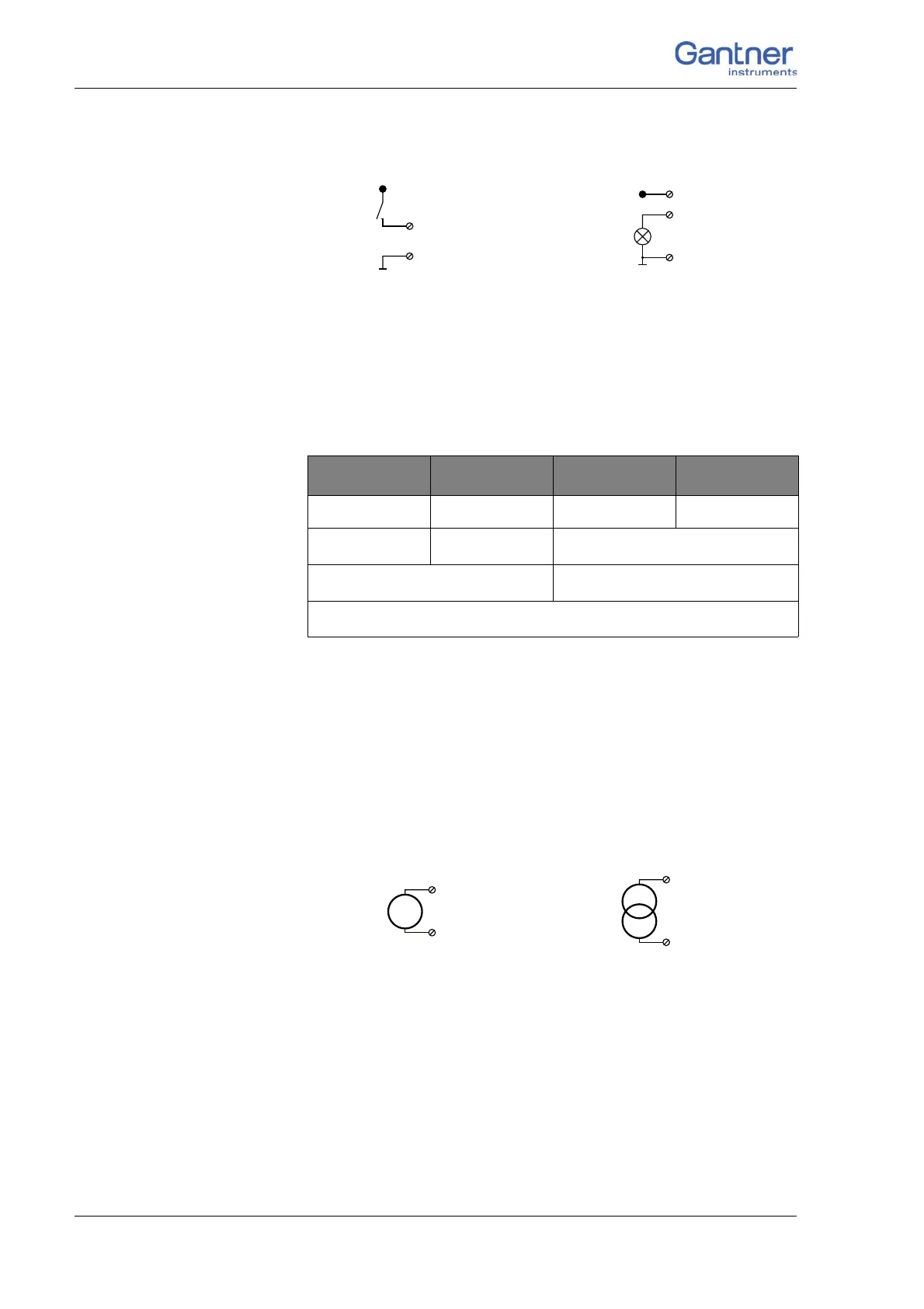
4 Connecting the modules → Q.bloxx A109: Connecting I/O and outputs
Fig. 4-65 A109, digital input and output, Plug 1.
The digital input is active (high level) when the applied signal
voltage lies above the (programmable) threshold.
Possible combinations of contact assignments for the inputs are
shown in th
e following table; refer also to the block diagrams for
Module D101.
1)
e.g. counter with additional input for counting direction
or 2-phase counter signals or frequency measurement
with direction detection (torque transducers)
2)
e.g. counter with additional inputs for counting direction,
zero reference and reset/enable for zero reference
4.16.2 Analog output, Plug 2
The analog outputs on Plug 2 supply voltage or current. Selection
is made via software.
Fig. 4-66 A109, output of voltage or current, Plug 2.
6 7 8 9
status status status status
status status
2-channel signal
1)
2-channel signal
1)
2-channel signal
1)
4-channel signal
2)
D
in
D
out
6, 7, 8, 9
+V
10 (0V)
1
10 (0V)
2, 3, 4, 5
+V
3, 5, 7, 9 (+)
4, 6, 8, 10 (–)
3, 5, 7, 9 (+)
4, 6, 8, 10 (–)

 Loading...