Vers. No. 6.1
90 Released: 25/04/2017
4 Connecting the modules → Q.bloxx A128: Connecting sensors
Further information on transducers and sensors can also be
found in Chapter 6 ff. page 135.
4.22.1 Voltage
You can measure voltages of up to ±1200 V
DC
. Here, various
input voltage ranges from ±40 V
DC
to ±1200 V
DC
are possible.
Voltages above 1200 V can damage the module.
Each module is tested with a test voltage of 5 kV
DC
for one min-
ute. A longer duration or a higher
voltage can damage the mod-
ule. In addition, each period of overvoltage reduces the service
life of the module.
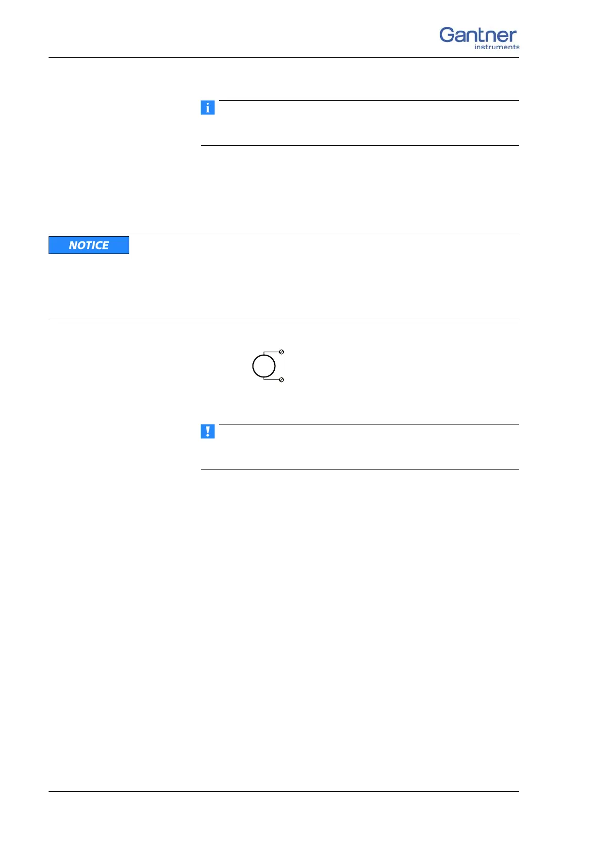
Fig. 4-89 A124, voltage measurement.
Voltages which exceed the admissible limits give incorrect mea-
surement data, because the input voltage is internally limited.

 Loading...