Q.series
Gantner Instruments GmbH
51
4 Connecting the modules → Q.bloxx A102: Connecting sensors and I/O
4.9 Q.bloxx A102: Connecting sensors and I/O
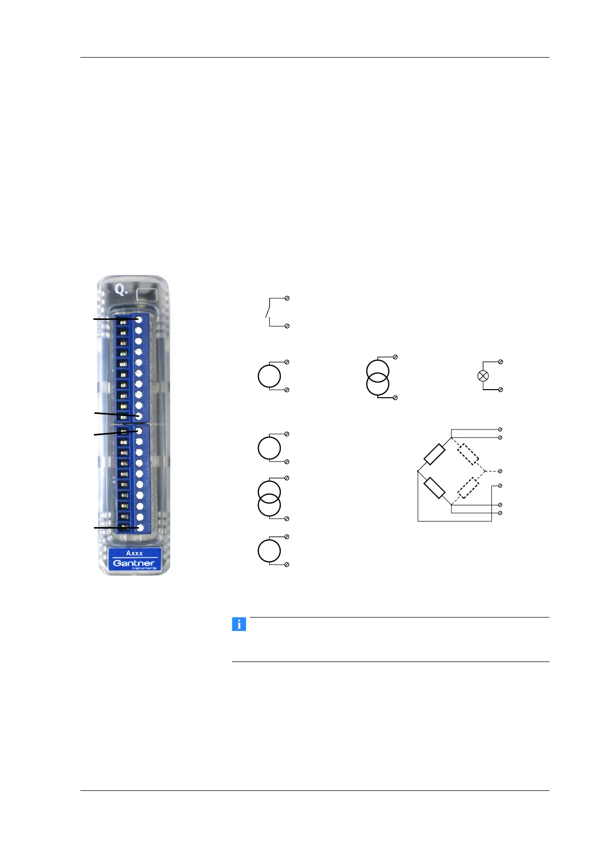
The Q.bloxx Module A102 has one electrically isolated analog
input, one analog output and two digital inputs or outputs electri-
cally isolated from the analog section. The assignment of both
connect
or strips is not identical. The plug number is specified in
the following. The connection terminals have numbers for identi-
fying the connections.
GND identifies the measurement ground of an input, 0 V and +V
re
fer to the (external) supply voltage connections. Measurement
ground and (module) supply voltage are electrically isolated in
the module.
Fig. 4-28 Pin assignment for Q.bloxx Module A102.
Further information on transducers and sensors can also be
found in Chapter 6 ff. page 135.
4.9.1 Voltage
You can measure voltages of up to 10 V via Plug 2.
Plug 1, outputs
Plug 1, inputs
Plug 2, inputs
I
IEPE
3, 4, 5, 6
+V
0V
7, 8
1A
Out+
2A
Out–
3DI 1
4DI 2
5DI 3
6DI 4
7DO 1
8DO 2
9A
MUX
10 B
MUX
1U
Exc+
2U
Sen+
3U
Sig+
4U
Sig–
5U
Sen–
6U
Exc–
7GND
8U
In
9I
In
10 TEDS
10110 1Plug 1Plug 2

 Loading...