Vers. No. 6.1
70 Released: 25/04/2017
4 Connecting the modules → Q.bloxx A108: Connecting sensors and I/O
Voltages which exceed the admissible limits produce incorrect
measurement data, because the inputs are protected against
overvoltages and limit the input voltage.
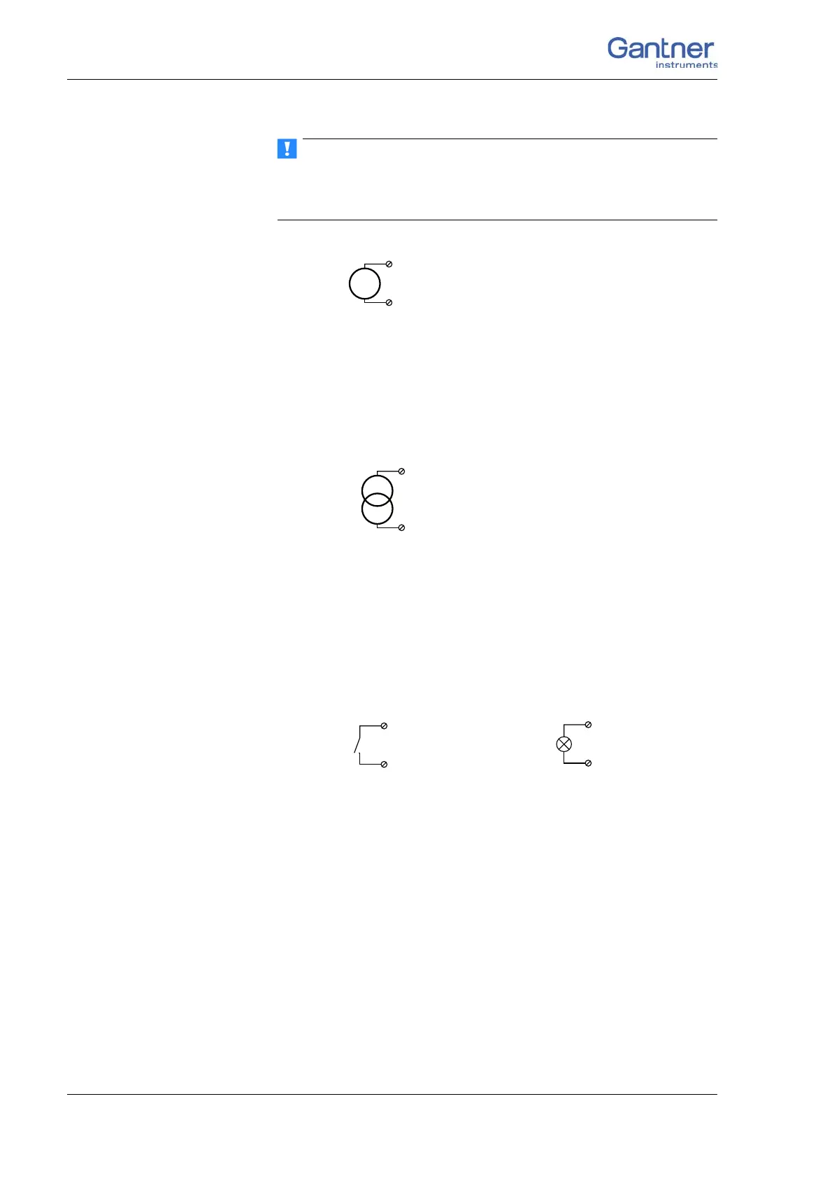
Fig. 4-61 A108, voltage measurement.
4.15.2 Current
For current measurement you need the Q.bloxx Terminal SR con-
necting plug containing the shu
nt resistances. This facilitates the
measurement of currents of up to 25 mA.
Fig. 4-62 A108, current measurement using the Q.bloxx Terminal
SR.
4.15.3 Digital input and output
On each connecting plug of the terminal version two contacts are
available in each case for one input and one output.
Fig. 4-63 A108, digital input and output.
The digital input is active (high level) when the applied signal
voltage lies above the threshold of 10 V.
3, 5, 7, 9 (A
In
+)
4, 6, 8, 10 (A
In
–)
3, 5, 7, 9 (A
In
+)
4, 6, 8, 10 (A
In
–)

 Loading...