Q.series
Gantner Instruments GmbH
89
4 Connecting the modules → Q.bloxx A128: Connecting sensors
4.22 Q.bloxx A128: Connecting sensors
The cables to be connected or disconnected may carry volt-
ages of up to 1200 V!
Before connecting or disconnecting cables make sure that
all sources of power are Locked Out.
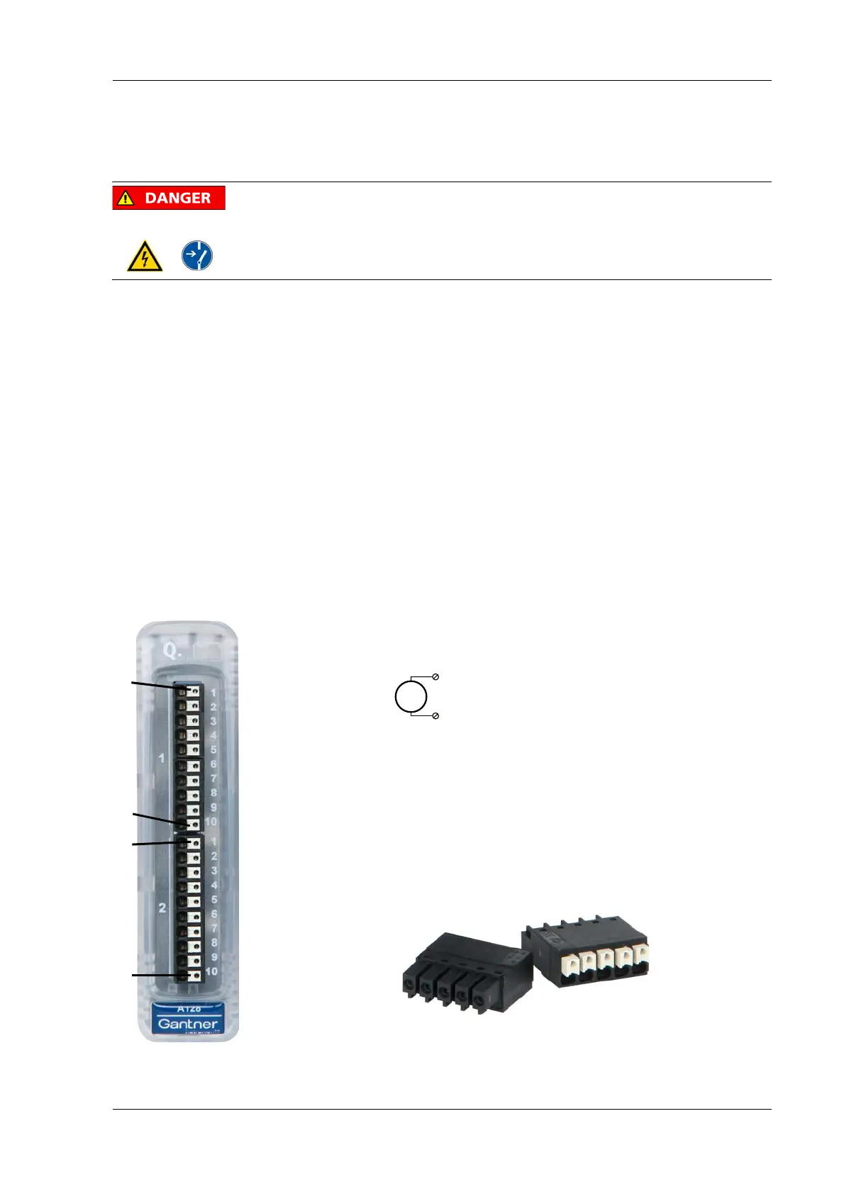
The Q.bloxx module A128 can be used in the categories CAT II up
to 1000 V and CAT III up to 600 V and has four electrically iso-
lated analog inputs. The pin assignment of the
two connector
strips is identical and the connection terminals have numbers for
identifying the connections. You will find the associated figures in
each case at the same place in the circuit diagrams, for example
each of the figures quoted in the second place belong to one pos-
sible connection method.
Measurement ground (–) and the (module) supply volta
ge are
electrically isolated in the module. NC signifies “No Connection”.
The plugs for the A128 module are 5-way plugs with push-in
spring technology, i.e. you can insert a solid wire or a fine-
stranded wire with a wire-end sleeve directly without screwing
(max. 1.5 mm
2
). With a screwdriver press on the white opener to
remove the connection.
Fig. 4-88 Pin assignment and plugs for the Q.bloxx module A128.
U
2, 7 (+)
4, 9 (–)
10110 1Plug 1Plug 2
1NC
2A
In
1+
3NC
4A
In
1–
5NC
6NC
7A
In
2+
8NC
9A
In
2–
10 NC
1NC
2A
In
3+
3NC
4A
In
3–
5NC
6NC
7A
In
4+
8NC
9A
In
4–
10 NC

 Loading...