Q.series
Gantner Instruments GmbH
71
4 Connecting the modules → Q.bloxx A109: Connecting I/O and outputs
4.16 Q.bloxx A109: Connecting I/O and outputs
The Q.bloxx Module A109 has four electrically isolated analog
outputs, four digital inputs and four digital outputs. The assign-
ment of both connector st
rips is not identical. The plug number is
specified in the following. The connection terminals have num-
bers for identifying the connections. You will find the
associated
figures in each case at the same place in the circuit diagrams, for
example each of the figures quoted in the second place belong to
one possible connection method.
The designations 0 V and +V refer to the (external) supply volt-
age connections, NC indicates “not assigned”. An
alog ground (–)
and the (external) supply voltage (0 V) are electrically isolated in
the mod
ule.
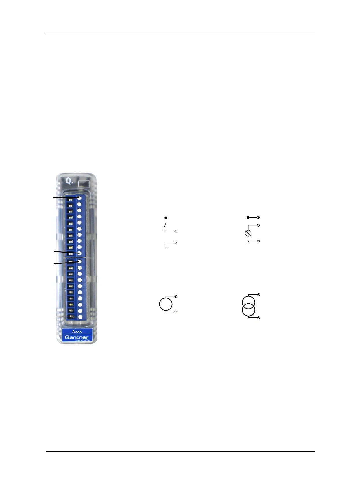
Fig. 4-64 Pin assignment for Q.bloxx Module A109.
4.16.1 Digital input and output, Plug 1
On Plug 1 contacts for four inputs and four outputs are available.
Since the inputs and outputs of this module are electrically iso-
lated from the supply voltage, you must also connect 0 V for the
inputs a
nd 0 V and a supply voltage (+V) for the outputs.
D
out
Input Output
6, 7, 8, 9
+V
10 (0V)
1
10 (0V)
2, 3, 4, 5
+V
3, 5, 7, 9 (+)
4, 6, 8, 10 (-)
I
3, 5, 7, 9 (+)
4, 6, 8, 10 (-)
Plug 1, digital inputs and outputs
Plug 2, analog outputs
1+V
2D
Out
1
3D
Out
2
4D
Out
3
5D
Out
4
6D
In
1
7D
In
2
8D
In
3
9D
In
4
10 0 V
1NC
2NC
3A
Out
1+
4A
Out
1–
5A
Out
2+
6A
Out
2–
7A
Out
3+
8A
Out
3–
9A
Out
4+
10 A
Out
4–
10110 1Plug 1Plug 2
+V must be between 12 V and 30 V

 Loading...