Q.series
Gantner Instruments GmbH
91
4 Connecting the modules → Q.bloxx D101: Connecting I/O
4.23 Q.bloxx D101: Connecting I/O
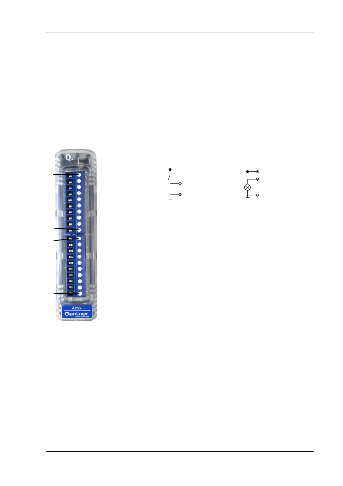
The Q.bloxx Module D101 has eight digital inputs and eight digi-
tal outputs. The pin assignment of the two connector strips is
id
entical and the connection terminals have numbers for identify-
ing the connections. You will find the associated figures in each
ca
se at the same place in the circuit diagrams, for example each
of the figures quoted in the second place belong to one possible
connection method.
The designations 0 V and +V refer to the (external) supply volt-
age connections.
Fig. 4-90 Pin assignment for Q.bloxx Module D101.
4.23.1 Digital input and output
On each connecting plug contacts for four inputs and four out-
puts are available. Since the inputs and o
utputs of this module
are electrically isolated from the supply voltage, you must also
connect 0V for the inputs and 0 V and a supply voltage (+V) for
the out
puts.
D
in
D
out
6, 7, 8, 9
+V
10 (0V)
1
10 (0V)
2, 3, 4, 5
+V
1+V
2D
Out
1
3D
Out
2
4D
Out
3
5D
Out
4
6D
In
1
7D
In
2
8D
In
3
9D
In
4
10 0 V
1+V
2D
Out
1
3D
Out
2
4D
Out
3
5D
Out
4
6D
In
1
7D
In
2
8D
In
3
9D
In
4
10 0 V
10110 1Plug 1Plug 2
+V must be between 12 V and 30 V

 Loading...