Vers. No. 6.1
92 Released: 25/04/2017
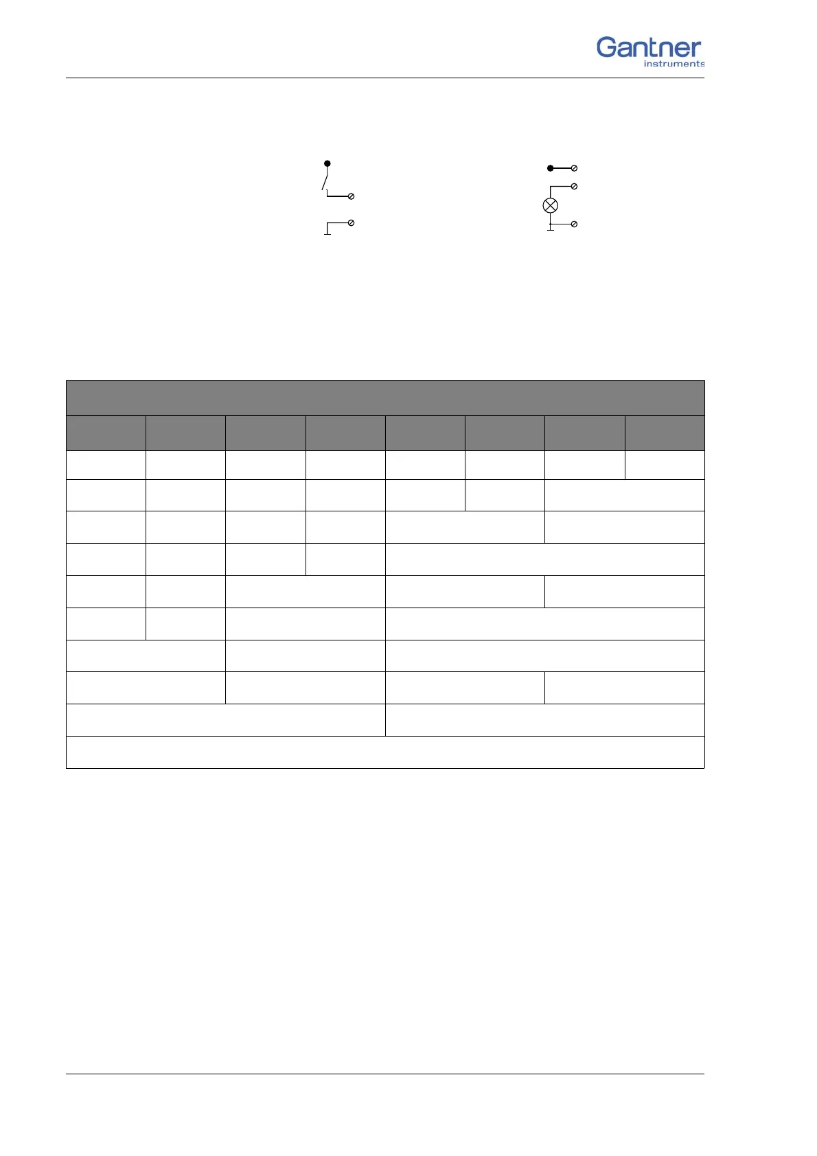
4 Connecting the modules → Q.bloxx D101: Connecting I/O
Fig. 4-91 D101, digital input and output.
The digital input is active (high level) when the applied signal
voltage lies above the (programmable) threshold.
The following table shows possible combinat
ions of contact
assignments for the inputs:
1)
e.g. counter with additional input for counting direction or 2-phase counter signals or fre-
quency measurement with direction detection (torque transducers)
2)
e.g. counter with additional inputs for counting direction, zero reference and reset/enable
for zero reference
3)
e.g. sensors with binary coding
The following block diagrams give you an overview of the possi-
ble circuits.
6, 7, 8, 9
+V
10 (0V)
1
10 (0V)
2, 3, 4, 5
+V
Plug.Contact
1.6 1.7 1.8 1.9 2.6 2.7 2.8 2.9
Status Status Status Status Status Status Status Status
Status Status Status Status Status Status
2-channel signal
1)
Status Status Status Status
2-channel signal
1)
2-channel signal
1)
Status Status Status Status
4-channel signal
2)
Status Status
2-channel signal
1)
2-channel signal
1)
2-channel signal
1)
Status Status
2-channel signal
1)
4-channel signal
2)
2-channel signal
1)
2-channel signal
1)
4-channel signal
2)
2-channel signal
1)
2-channel signal
1)
2-channel signal
1)
2-channel signal
1)
4-channel signal
2)
4-channel signal
2)
8-channel signal
3)

 Loading...