Vers. No. 6.1
28 Released: 25/04/2017
4 Connecting the modules → Connecting the power supply
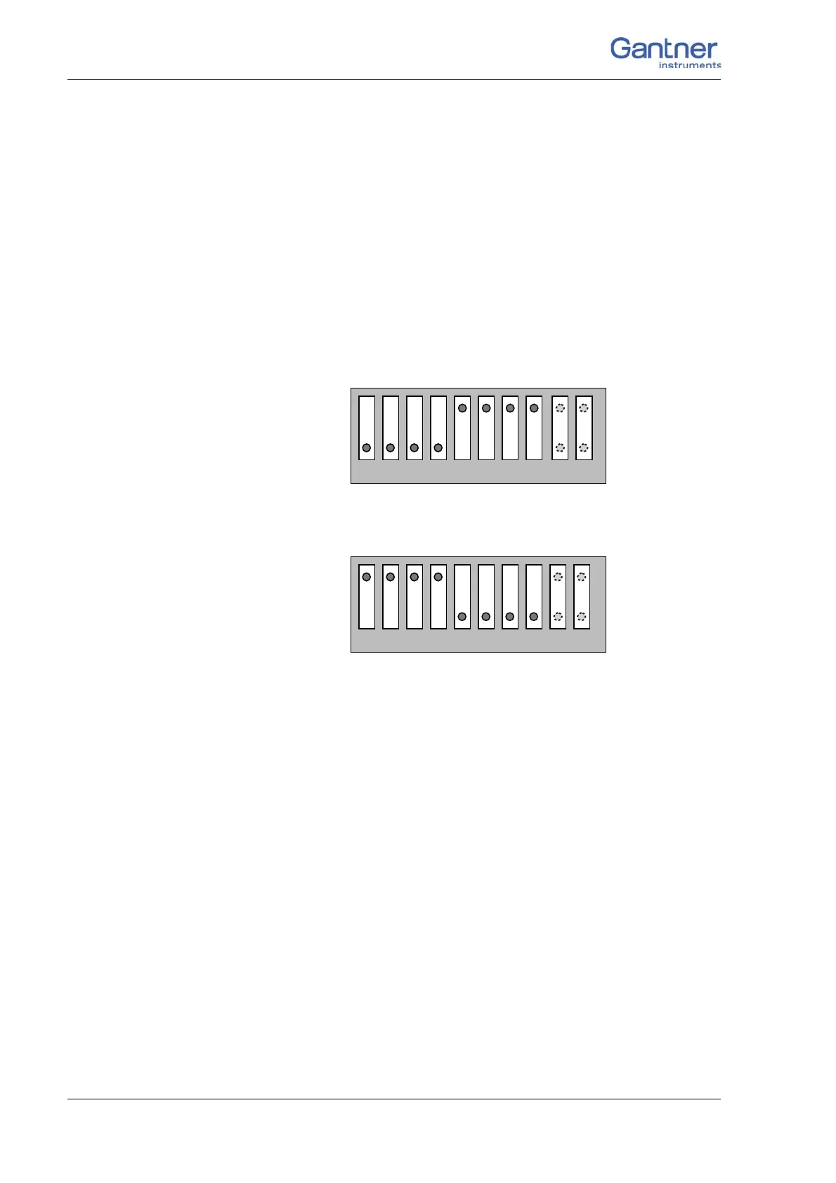
1. The interface lines are connected through 1:1 from left to
right.
The DIP switches 1 to 4 are OFF and the DIP switches 5 to 8
are ON (factory setting).
2. The interface lines are crossed.
The DIP switches 1 to 4 are ON and the DIP switches 5 to 8
are OFF.
T
he DIP switches 9 and 10 (far right) have no function so their
sett
ings do not matter.
➡ Setting of all switches to OFF or all switches to ON is not admis-
sible.
Fig. 4-4 The DIP switch position for a 1:1 connection (factory set-
ting).
Fig. 4-5 The DIP switch position for crossed connection (interface
lines for UART 1 and UART 2 are crossed).
4.2 Connecting the power supply
For the power supply an unregulated direct voltage between 10
and 30 volts is required, which is connected to the contacts 5 and
6 from abov
e the base. Fig. 4-6 shows the pin assignment. Each
module requires a power of approx. 2 W in addition to the power
supplied f
or the connected transducers. The power required is
almost constant over the complete voltage range.

 Loading...