Q.series
Gantner Instruments GmbH
57
4 Connecting the modules → Q.bloxx A104: Connecting sensors
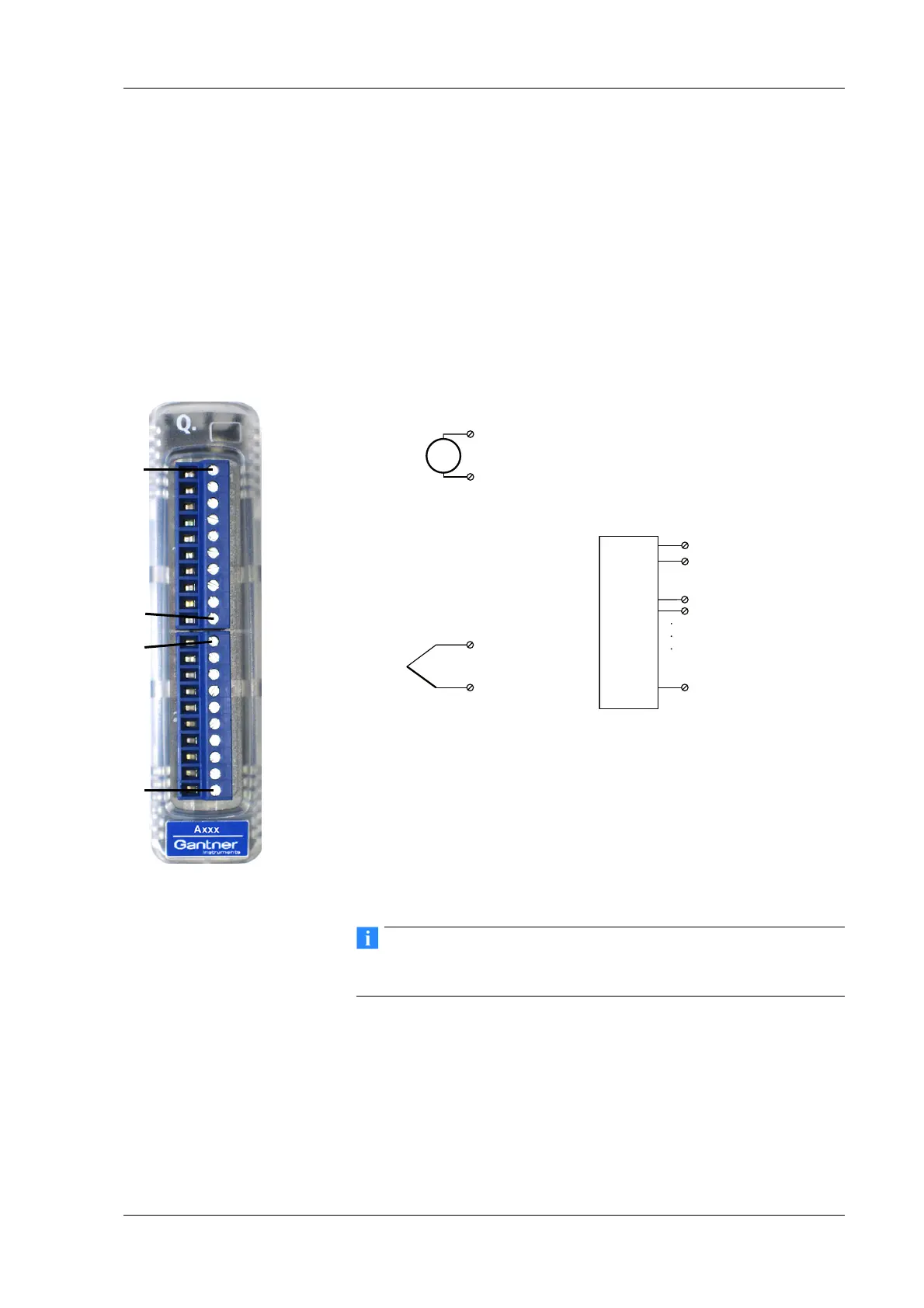
4.11 Q.bloxx A104: Connecting sensors
The Q.bloxx Module A104 has eight electrically isolated analog
inputs for thermocouples or voltages. The pin assignment of the
two connector strips is identical and the connection terminals
have numbers for identifying the connections. You will find the
associated figures in each case at the same place in the circuit
diagrams, for example each of the figures quoted in the second
place belong to one possible connection method.
Measurement ground (–) and the (module)
supply voltage are
electrically isolated in the module.
Fig. 4-40 Pin assignment for Q.bloxx Module A104.
Further information on transducers and sensors can also be
found in Chapter 6 ff. page 135.
4.11.1 Voltage
You can measure voltages of up to 80 mV.
U
3, 5, 7, 9 (+)
4, 6, 8, 10 (–)
4, 6, 8, 10 (–)
3, 5, 7, 9 (+)
1CJC+
2CJC–
3A
In
1+
4A
In
1–
5A
In
2+
6A
In
2–
7A
In
3+
8A
In
3–
9A
In
4+
10 A
In
4–
1CJC+
2CJC–
3A
In
1+
4A
In
1–
5A
In
2+
6A
In
2–
7A
In
3+
8A
In
3–
9A
In
4+
10 A
In
4–
10110 1Plug 1Plug 2
Q.bloxx Terminal CJC
CJC–
CJC+

 Loading...