EasyManuals Logo

Gantner Q Series User Manual

Gantner Q Series
150 pages
To Next Page IconTo Next Page
To Previous Page IconTo Previous Page
Page #50 background imageLoading...
Page #50 background image
Vers. No. 6.1
50 Released: 25/04/2017
4 Connecting the modules Q.bloxx A101: Connecting sensors and I/O
Fig. 4-26 A101, measurement with IEPE or ICP
®
sensors.
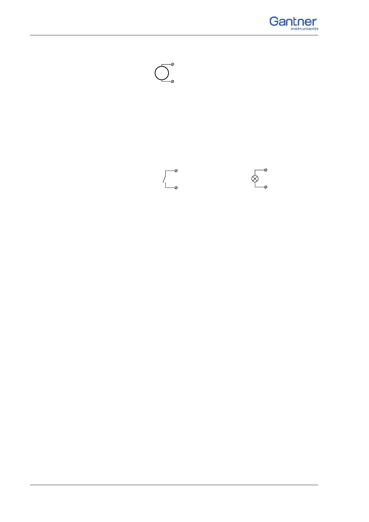
4.8.9 Digital input and output
On each connecting plug a contact is available for an input or out-
put. You can use the appropriate function depending on the wir-
in
g.
Fig. 4-27 A101, digital input and output.
The digital input is active (high level) when the applied signal
voltage lies above the threshold of 10 V.
IEPE
7 (GND)
8 (+)
Input Output
D
in
D
out
10
+V
0V
10

Table of Contents

Questions and Answers:

Question and Answer IconNeed help?

Do you have a question about the Gantner Q Series and is the answer not in the manual?

Gantner Q Series Specifications

General IconGeneral
BrandGantner
ModelQ Series
CategoryControl Unit
LanguageEnglish

Related product manuals