Vers. No. 6.1
94 Released: 25/04/2017
4 Connecting the modules → Q.bloxx D104: connecting digital inputs
4.24 Q.bloxx D104: connecting digital inputs
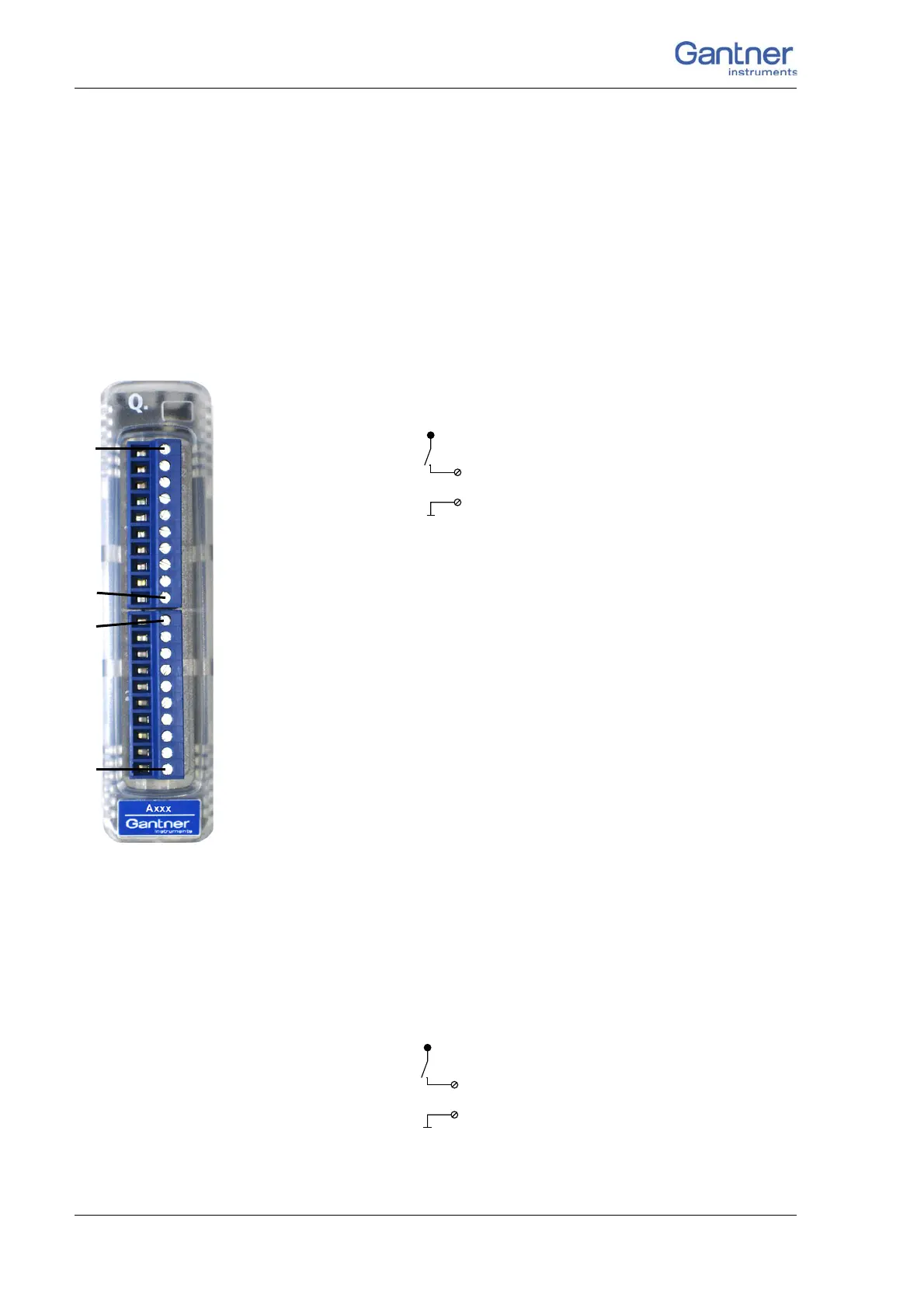
The Q.bloxx Module D104 has sixteen digital inputs. The pin
assignment of the two connector strips is identical and the con-
nection terminals have numbers fo
r identifying the connections.
You will find the associated figures in each case at the same place
in the circuit diagrams, for example each of the figures quoted in
the second place belong to one possible connection method.
The designations 0 V and +V refer to the (external) supply volt-
age connections, NC indicates “not assigned”.
Fig. 4-92 Pin assignment for Q.bloxx Module D104.
4.24.1 Digital input
On each connecting plug contacts for eight inputs are available.
Since the inputs of this module are electrically isolated from the
power supply, you must also connect 0 V and a supply voltage
(+V).
Fig. 4-93 D104, digital input.
2, 3, 4, 5, 6, 7, 8, 9
+V
10 (0V)
1NC
2D
In
1
3D
In
2
4D
In
3
5D
In
4
6D
In
5
7D
In
6
8D
In
7
9D
In
8
10 0 V
1NC
2D
In
1
3D
In
2
4D
In
3
5D
In
4
6D
In
5
7D
In
6
8D
In
7
9D
In
8
10 0 V
10110 1Plug 1Plug 2
+V must be between 12 V and 30 V
D
in
2, 3, 4, 5, 6, 7, 8, 9
+V
10 (0V)

 Loading...