Q.series
Gantner Instruments GmbH
97
4 Connecting the modules → Q.bloxx D107: Connecting digital inputs
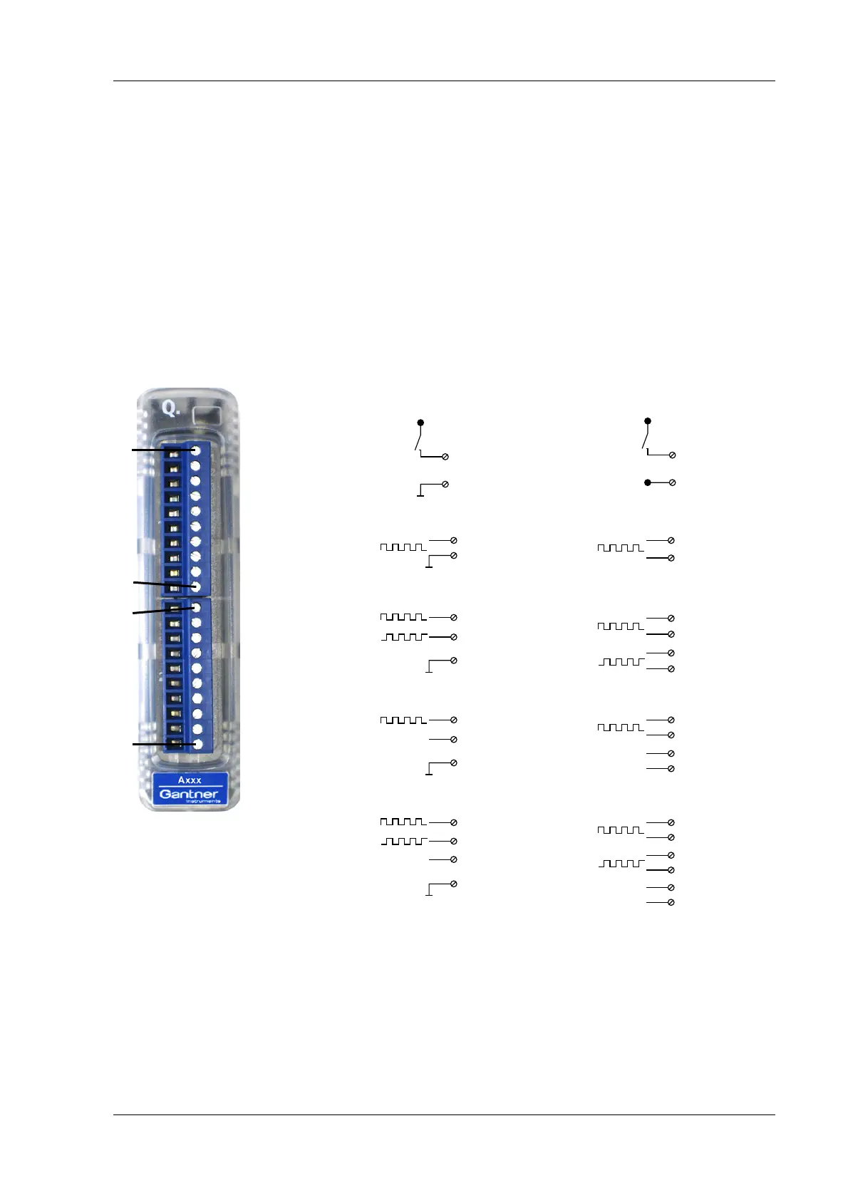
4.26 Q.bloxx D107: Connecting digital inputs
The Q.bloxx Module D107 has sixteen digital inputs. The pin
assignment of the two connector strips is identical and the con-
nection terminals have numbers for identifying the connections.
You will find
the associated figures in each case at the same place
in the circuit diagrams, for example each of the figures quoted in
the second place belong to one possible connection method.
The designations 0 V (GND) and +V re
fer to the supply voltage
connections for supplying the sensors. NC signifies “No Connec-
tion”. Both terminals are electrically isolated from one another
and fr
om the module supply voltage.
Fig. 4-96 Pin assignment and circuit variants for the Q.bloxx Mod-
ule D107.
4.26.1 Digital input
On each connecting plug contacts for three inputs are available.
You can use the inputs as a differential input or as a ground-ref-
erenced (single-ended) input. Since in each case t
he inputs termi-
D
in
2, 5, 8
+V
10 (0V, GND)
1 +5 V/150 mA
2A1+
3A1‒
4NC
5B1+
6B1‒
7NC
8Z1+
9Z2‒
10 GND (0 V)
1 +5 V/150 mA
2A1+
3A1‒
4NC
5B1+
6B1‒
7NC
8Z1+
9Z2‒
10 GND (0 V)
10110 1Plug 1Plug 2
D
in
+V
2, 5, 8
3, 6, 9
Ground-referenced
Differential
D
in
D
in
+/-
D
in
0-Ref.
D
in
2, 5, 8
3, 6, 9
2, 5
3, 6
2, 5
3, 6
2
3
5, 8
6, 9
5, 8
6, 9
5
6
8
9
2, 5, 8
10 (0V, GND)
10 (0V, GND)
10 (0V, GND)
10 (0V, GND)
2, 5
5, 8
2, 5
5, 8
2
5
8

 Loading...