Vers. No. 6.1
114 Released: 25/04/2017
5 Configuration → Specifying digital inputs/outputs
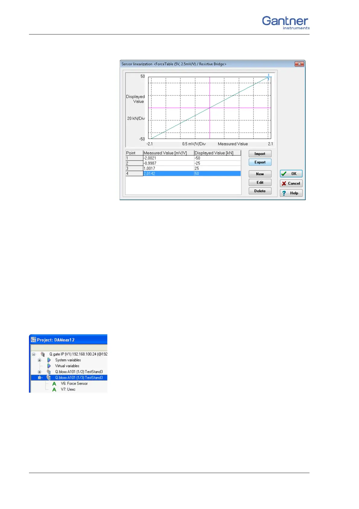
Fig. 5-7 Entering the scaling table.
If the data are present in an Excel file, you can also import a file
in the format Excel 97-2003-Workbook (*.xls).
Alternatively to entering a unit in step 5, you can leave the elec-
trical unit of the sensor as it is and enter the table in this unit,
e.g. mV/V measured
value and mV/V
displayed value. You can
then define the unit displayed for the measurement in the For-
mat/balance column.
Do not forget
to save these settings in the module and the Test
Controll
er (refer to Section 5.3.1, Setting sensor parameters,
page 10
7).
5.4 Specifying digital inputs/outputs
In order to set parameters you should be connected to the mod-
ule and have called the configuration program (ICP 1
00 which is
started automatically by test.commander):
Mark a module and
select Configuration from the context menu or double
click on a
module or module signal (variable) to start the configuration pro-
gram. Then carry out all the module settings in the window of this
program.
You can however also configure a project without a direct con-
nection and then, once you have established the connection, load
th
e correspondi
ng files into the modules and load Test Controller.
All module signals are defined as variables. Therefore, for the
en
try acti
vate the tab Variable definition in the configuration
program.

 Loading...