Q.series
Gantner Instruments GmbH
115
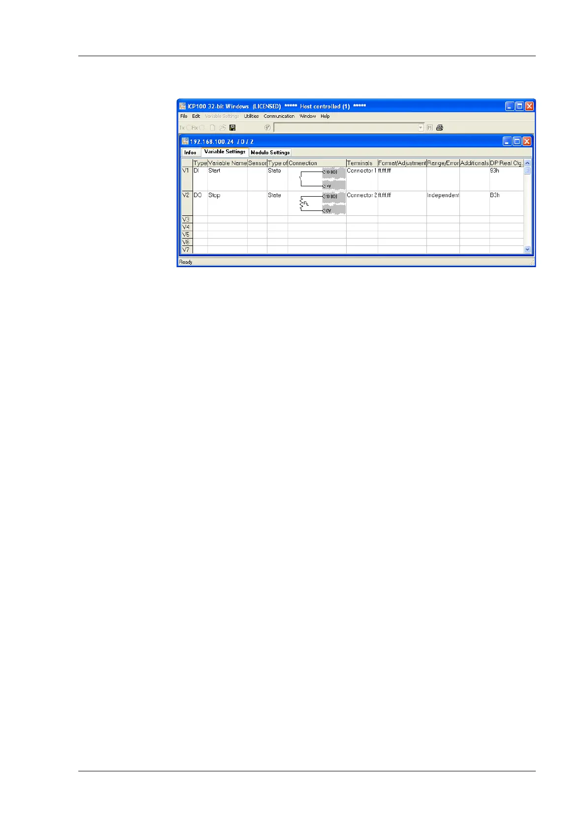
5 Configuration → Specifying digital inputs/outputs
Fig. 5-8 Dialog with configuration for digital input and output.
Procedure 1. Click in the column Type of the first row (V1 = Variable 1) or
mark the row (click on V1) and use Variable definition >
Type.
2. Select Digit. input or Digit. output.
The
column Wiring diag
ram shows you the pin assignment.
With more than one input the first inputs are also always
occupied first (first Plug 1, then Plug 2, etc.). Check for cor-
rect connection.
3. Click in the column Variable name and al
locate a name iden-
tifying the signal.
4. At a digital outp
ut click in the column Type of and specify
whether you want to use the output as Status indicator, Sta-
tus field or Process output.
Process output: Th
e output monitors a module signal and
changes the output level under certain conditions. Click in the
column Other and specify the type of alarm monitoring.
You can specify up to four alarm conditions.
When one of
the conditions is satisfied, the alarm signal is triggered.
To the left above the graphical displays select the levels at
which swi
tching is to occur and how they are to switch.
Enter the values for the switching thresholds in the
(scaled) unit of the selected signal. Use either fixed values
(constants) or arrange for the values to be determined by
other variables.
Status indicator: The
output can be set via a command from
the Test Controller, e.g. via a PROFIBUS-DP command. Click
in the column Other and specify the type of alarm monitoring.
5. Click in the column Format/balanc
e to specify the transfer
format.

 Loading...