Vers. No. 6.1
88 Released: 25/04/2017
4 Connecting the modules → Q.bloxx A127: Connecting sensors
Further information on transducers and sensors can also be
found in Chapter 6 ff. page 135.
4.21.1 Voltage
You can measure voltage differences of up to ±1200 V. Here, var-
ious input voltage ranges from ±40 V
DC
to ±1200 V
DC
are possi-
ble. The voltage level (the potential) may be up to 1200 V
DC
.
Voltages above 1200 V can damage the module.
Each module is tested with a test voltage of 5 kV
DC
for one min-
ute. A longer duration or a higher
voltage can damage the mod-
ule. In addition, each period of overvoltage reduces the service
life of the module.
Fig. 4-86 A127, measurement of voltage.
Voltages which exceed the admissible limits give incorrect mea-
surement data, because the input voltage is internally limited.
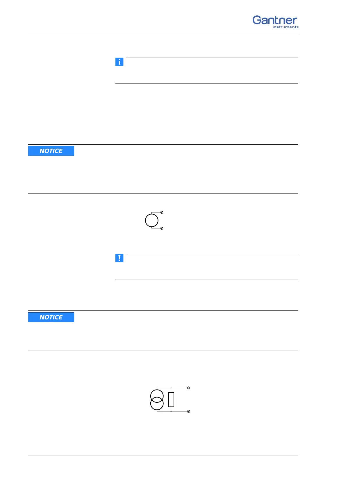
4.21.2 Current
Confusing the current and voltage inputs can damage the module
and/or the external load resistance.
Make sure that no high voltages are applied to the current inputs.
The voltage drop must not be beyond ±2.4 V.
You need an (external) shunt resistance for the current measu
re-
ment, refer also to Section 6.5, page 147.
Fig. 4-87 A127, current measurement using an external shunt
resistance.

 Loading...