EasyManuals Logo

Gantner Q Series User Manual

Gantner Q Series
150 pages
To Next Page IconTo Next Page
To Previous Page IconTo Previous Page
Page #54 background imageLoading...
Page #54 background image
Vers. No. 6.1
54 Released: 25/04/2017
4 Connecting the modules Q.bloxx A102: Connecting sensors and I/O
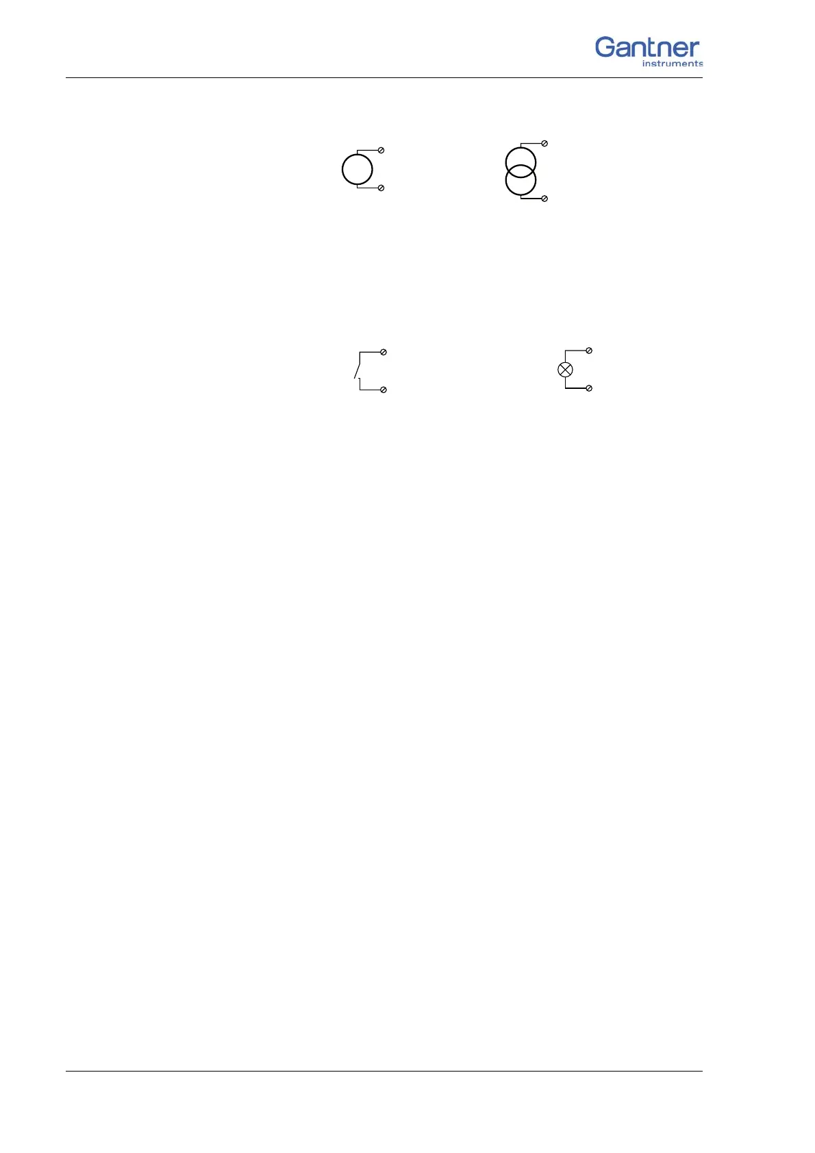
Fig. 4-34 A102, output of voltage or current, Plug 1.
4.9.7 Digital input and output
Contacts for four inputs and two outputs are available on Plug 1.
Fig. 4-35 A102, digital input and output, Plug 1.
The digital input is active (high level) when the applied signal
voltage lies above the threshold of 10 V.
U
1 (+)
2 (–)
I
1 (+)
2 (–)
Input Output
D
in
D
out
3, 4, 5, 6
+V
0V
7, 8

Table of Contents

Questions and Answers:

Question and Answer IconNeed help?

Do you have a question about the Gantner Q Series and is the answer not in the manual?

Gantner Q Series Specifications

General IconGeneral
BrandGantner
ModelQ Series
CategoryControl Unit
LanguageEnglish

Related product manuals