Q.series
Gantner Instruments GmbH
85
4 Connecting the modules → Q.bloxx A124: Connecting sensors
4.20 Q.bloxx A124: Connecting sensors
The cables to be connected or disconnected may carry volt-
ages of up to 1200 V!
Before connecting or disconnecting cables make sure that
all sources of power are Locked Out.
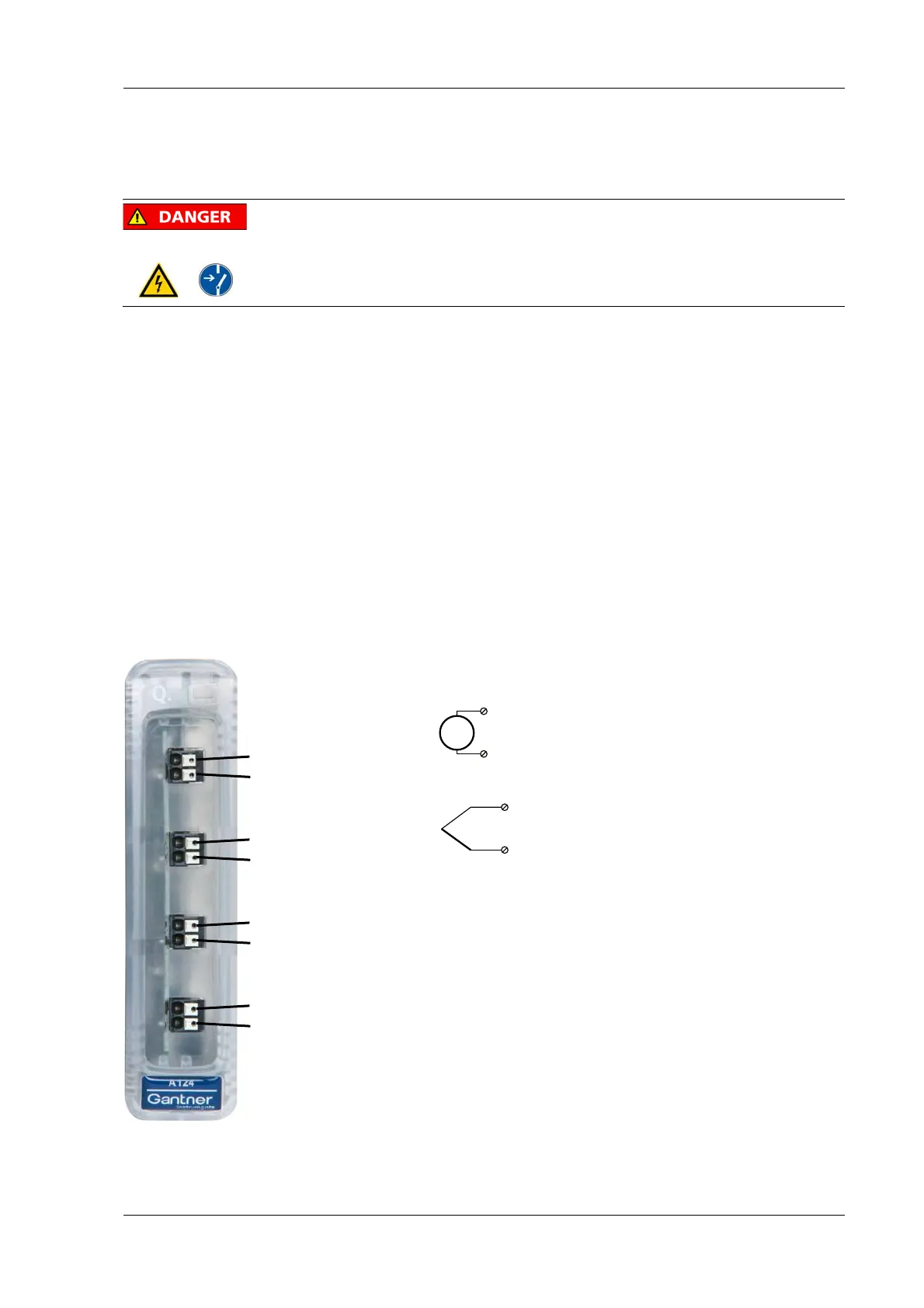
The Q.bloxx module A124 can be used in the categories CAT II up
to 1000 V and CAT III up to 600 V and has four electrically iso-
lated analog inputs for thermocouples. The terminal assignment
is
identical. You will find the associated figures in each case at
the same place in the circuit diagrams, for example each of the
figures quoted in the second place belong to one possible connec-
tion method.
Measurement ground (–) and the (module) supply volta
ge are
electrically isolated in the module. The plugs for the A124 module
are 2-way plugs with push-in spring technology, i.e. you can
insert a solid wire or a fine-stranded wire with a wire-end sleeve
directly without screwing (max. 1.5 mm
2
). The plugs are perma-
nently joined to the housing
and cannot be removed. With a
screwdriver press on the white opener to remove the connection.
Fig. 4-82 Pin assignment for Q.bloxx Module A104.
4, 9 (–)
2, 7 (+)
2A
In
1+
4A
In
1–
U
2, 7 (+)
4, 9 (–)
7A
In
2+
9A
In
2–
2A
In
3+
4A
In
3–
7A
In
4+
9A
In
4–

 Loading...