Q.series
Gantner Instruments GmbH
63
4 Connecting the modules → Q.bloxx A106: Connecting sensors and I/O
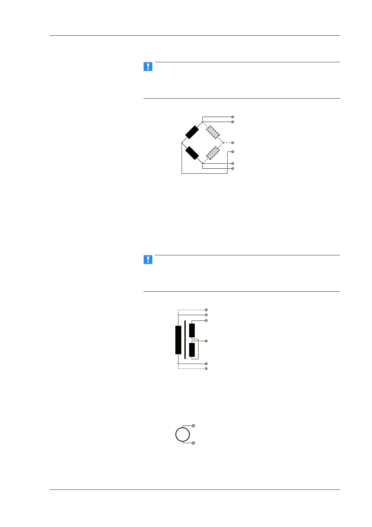
During the configuration set CF 4800 Hz (carrier frequency) in
the Type column; inductive sensors cannot be operated with
direct voltage (DC) or 600 Hz carrier frequency.
Fig. 4-48 A106, measurement with inductive full and half bridges.
4.13.4 LVDT, RVDT
With (inductive) LVDTs or RVDTs all connections can be occu-
pied, but you can also connect without sense leads and state this
in th
e Type column when configuring the module.
The bridge excitation voltage can be 2.5 V or 5 V.
During the configuration set CF 4800 Hz (carrier frequency) in
the Type column; inductive sensors cannot be operated with
direct voltage (DC) or 600 Hz carrier frequency.
Fig. 4-49 A106, measurement with LVDTs and RVDTs.
4.13.5 Analog output
An analog voltage output is available on each connecting plug.
Fig. 4-50 A106, analog output.

 Loading...