190-01115-01 G3X™/G3X Touch™ Avionics Installation Manual
Rev. AV Page 11-3
11.4.2 Unit Installation
Fabrication of a wiring harness is required. Sound mechanical and electrical methods and practices are
recommended for installation of the GMC 307. Refer to Section 2.3
for wiring considerations, and to
Section 23.5
for pinouts.
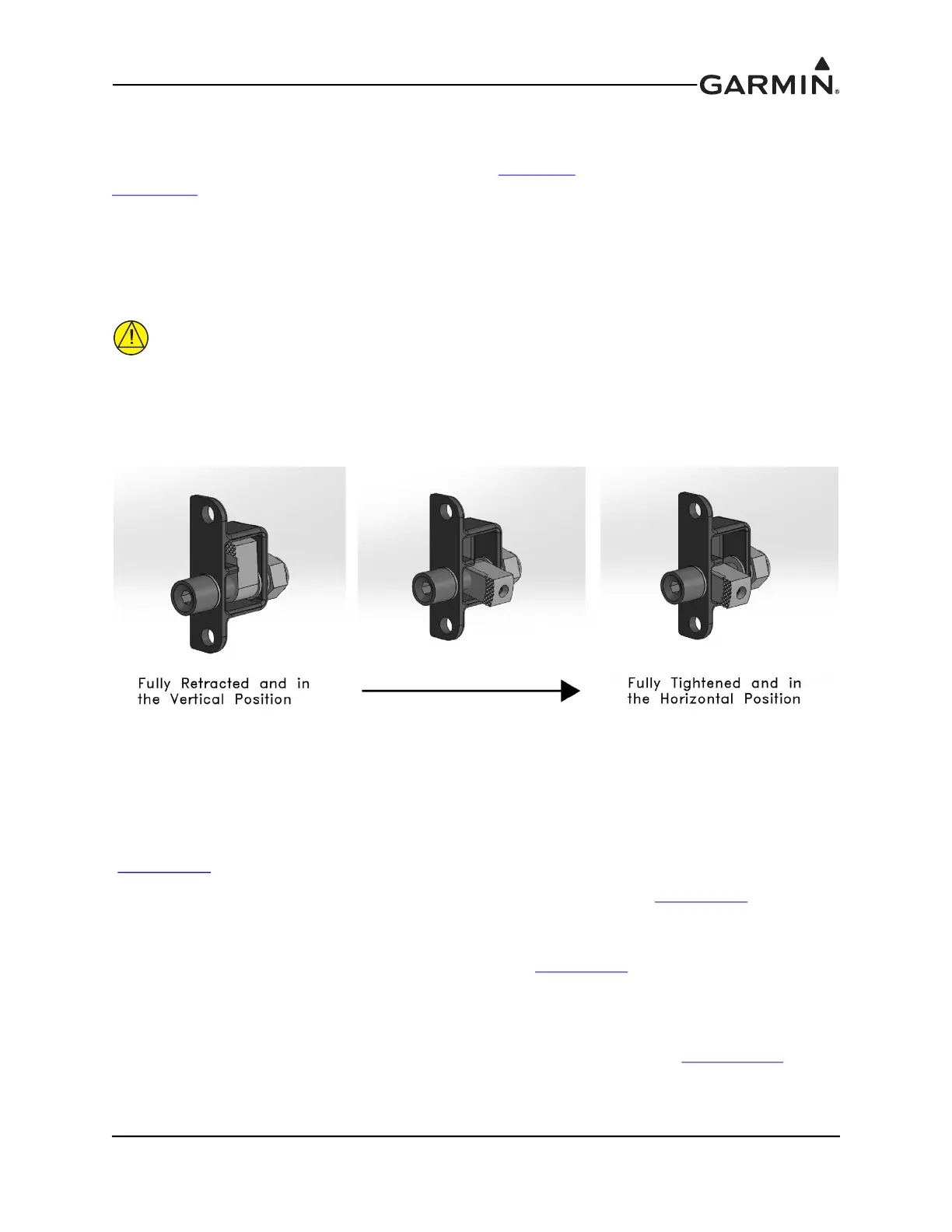
1. Per Figure 11-2, make sure the pawl latch fasteners are fully retracted and in the vertical position.
2. Hold the unit flush with the instrument panel.
3. Using a 3/32" hex drive tool turn each of the two pawl latches clockwise until tightened to
20 +/-2 in-lbs. When tightened, the pawl latches are in the horizontal position.
CAUTION
To remove the GMC from the instrument panel, turn each of the two pawl latches
counterclockwise. After initially breaking the pawl latch loose, continue to loosen while
not exceeding 15 in-lbs of torque.
Figure 11-2. Pawl Latch
11.4.3 Wiring
The 15 pin connector, pins, and backshell supplied in the GMC 307 installation kit are used to add wiring
for the GMC 307.
It is recommended that a 2 Amp fuse or circuit breaker be used to supply power to the GMC 307
(Figure 24-1.7
). Backup power is optional.
The GMC 307 is connected through RS-232 to any GDU™ 37X/4XX display (Figure 24-1.7
). The
selected GDU RS-232 channel must be configured for “Garmin Instrument Data”.
If the installation includes a Garmin integrated autopilot using GSA 28 servos, the GMC 307 installation
also includes an RS-232 connection to the GSA 28 roll servo (Figure 24-1.7
). GMC 307 RS-232 channel 1
must be connected to any one of the available RS-232 channels on one of the GDU 37X/4XX units. The
GMC 307 RS-232 channel 2 must be connected to the GSA 28 roll servo RS-232 channel 1 if this roll
servo is installed.
For installations using a non-Garmin autopilot with a GMC 307 controller, refer to Figure 24-2.25
.