190-01115-01 G3X™/G3X Touch™ Avionics Installation Manual
Rev. AV Page 23-41
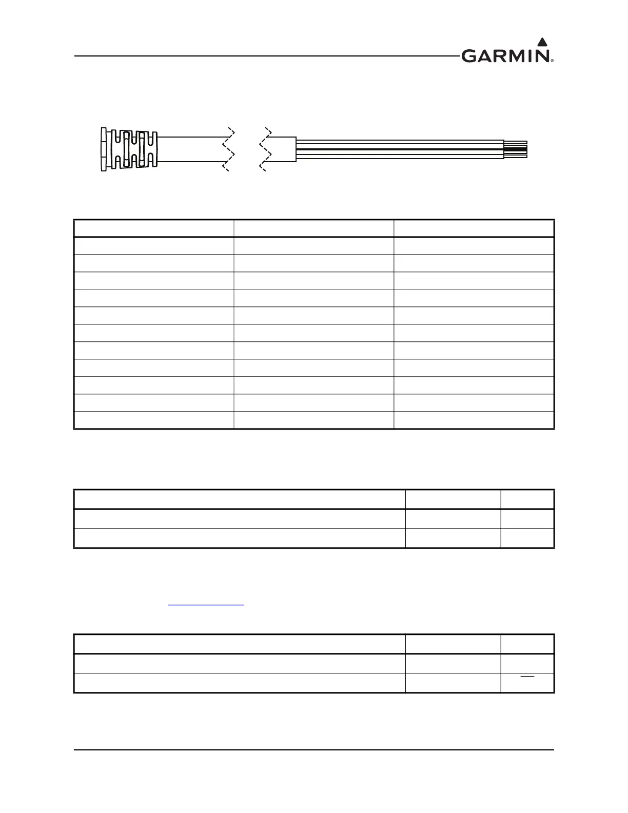
23.6 GI 260 (AOA Indicator)
23.6.1 Pigtail Connections
Figure 23-17 GI 260 Pigtail Harness
23.6.2 Power
AIRCRAFT POWER 1 and POWER GROUND are connected to a 14/28 VDC supply..
23.6.3 CAN Bus
The CAN Bus conforms to the BOSCH standard for Controller Area Network 2.0-B, and complies with
ISO 11898. Refer to Section 2.3.1.3.2
for details on wiring the CAN bus. Using the CAN Bus is the
preferred data interconnect for the GI 260 in a G3X system.
Pin Name Wire Color I/O
AIRCRAFT POWER RED IN
POWER GROUND BLACK --
CAN HI BLUE I/O
CAN LO VIOLET I/O
SHIELD GND BLACK HEAT SHRINK --
RS-232 RX YELLOW IN
RS-232 TX BROWN OUT
DC LIGHTING BUS GRAY IN
RESERVED WHITE --
RESERVED GREEN --
AUDIO SHIELD BLACK HEAT SHRINK --
Pin Name Wire Color I/O
AIRCRAFT POWER 1 RED In
POWER GROUND BLACK --
Pin Name Wire Color I/O
CAN HI BLUE I/O
CAN LO VIOLET I/O