190-01115-01 G3X™/G3X Touch™ Avionics Installation Manual
Rev. AV Page 23-52
23.12 GPS 20A (WAAS GPS Position Source)
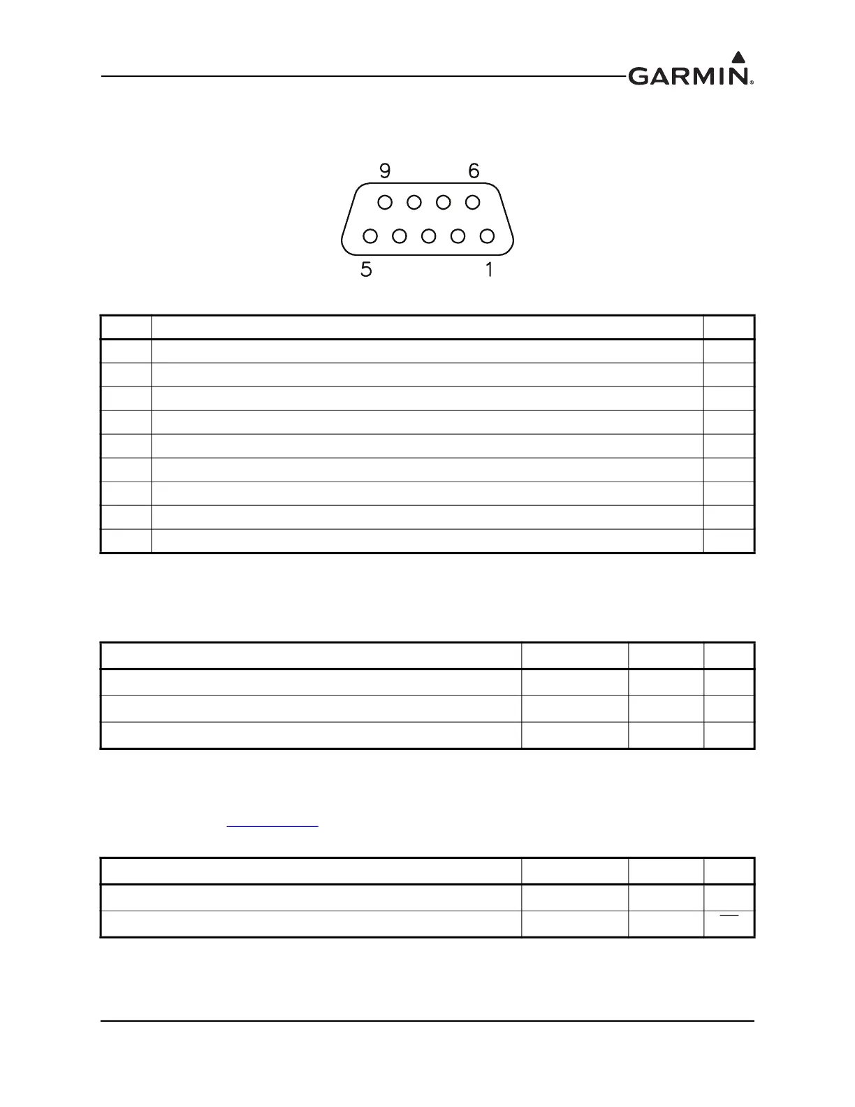
23.12.1 J201 Connector
Figure 23-23 J201 on GPS 20A, as viewed looking at connector on unit
23.12.2 Power Function
This section covers the power input requirements. The GPS 20A is compatible with 14V and 28V systems.
AIRCRAFT POWER 1 and AIRCRAFT POWER 2 are “diode ORed” to provide power redundancy.
23.12.3 CAN Bus
The CAN Bus conforms to the BOSCH standard for Controller Area Network 2.0-B, and complies with
ISO 11898. Refer to Section 2.3.1.3
for details on wiring the CAN bus. Using the CAN Bus is the preferred
data interconnect for the GPS 20A in a G3X system.
Pin Pin Name I/O
1 CAN-H I/O
2 CAN-L I/O
3 RS-232 TX 2 Out
4 RS-232 RX 1 In
5 RS-232 TX 1 Out
6 RS-232 GROUND --
7 AIRCRAFT POWER 1 In
8 AIRCRAFT POWER 2 In
9 POWER GROUND --
Pin Name Connector Pin I/O
AIRCRAFT POWER 1 J201 7 In
AIRCRAFT POWER 2 J201 8 In
POWER GROUND J201 9 --
Pin Name Connector Pin I/O
CAN-H J201 1 I/O
CAN-L J201 2 I/O