190-01115-01 G3X™/G3X Touch™ Avionics Installation Manual
Rev. AV Page 10-2
10.2.2 Additional Equipment Required
The following accessories are not provided with the GMC 305 unit. The Installation Kit (Table 10-2) is
required to install the unit. The Installation Kit includes the Connector Kit (Table 10-3) and the Mounting
Kit (Table 10-4
).
10.3 General Specifications
See Section 2.2 for power/current specifications, and Section 2.4.1 for dimension/weight specifications.
10.4 Mounting and Wiring Requirements
10.4.1 Fasteners
The GMC 305 is installed using the four #6-32 threaded cap screws supplied in the GMC 305 installation
kit using a 3/32” hex wrench. The instrument panel may be drilled and tapped for the #6-32 screws, or the
four anchor nuts supplied in the installation kit may be installed using flush-mount rivets.
10.4.2 Panel Cutout Template
Figure 10-5
can be used as a template when marking the panel for cutout. Dimensions on the figure are to
verify accuracy of printout only, see Figure 10-4
for complete cutout dimensions. A .dxf version of the
drawing is also available for download at https://support.garmin.com/support/manuals
.
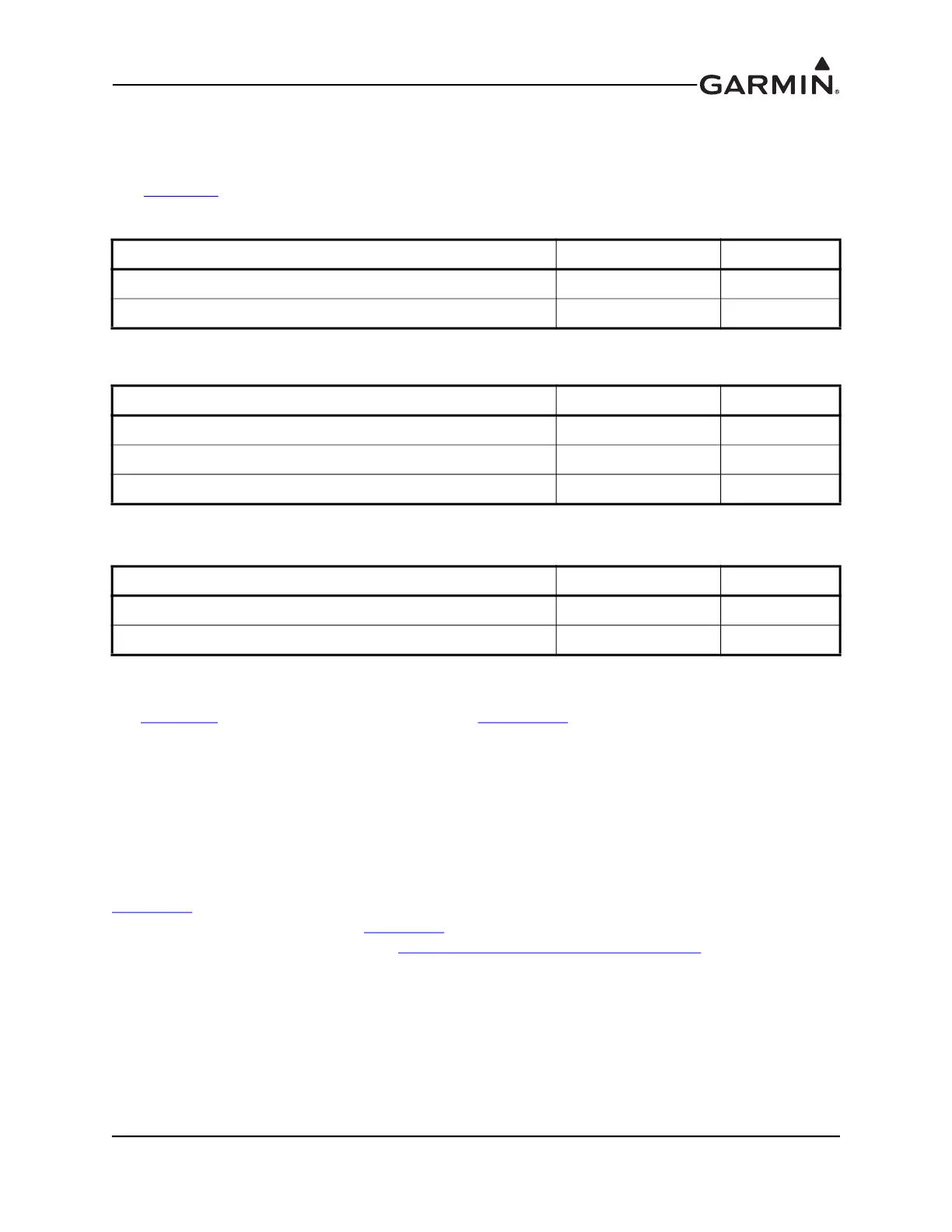
Table 10-2 Contents of GMC 305 Installation Kit (010-12034-00)
Item Garmin P/N Quantity
Connector Kit, 15 Pin, Hi Density Male w/Jackscrews 011-01824-00 1
Mounting Kit, GMC 305 011-03242-00 1
Table 10-3 Contents of Connector Kit (011-01824-00)
Item Garmin P/N Quantity
Backshell w/Hdw, Jackscrew, 9/15 Pin 011-01855-00 1
Connector, Male, High Density D-Sub,15 CKT 330-00366-15 1
Contact, Pin, Military Crimp, Size 22D 336-00021-00 12
Table 10-4 Contents of Mounting Kit (011-03242-00)
Item Garmin P/N Quantity
Nut, Self-Locking, Plate, One Lug, 6-32 210-00104-04 4
Screw, Machine, Panel Mounting, 0.550", Black
211-00169-01 4