190-01115-01 G3X™/G3X Touch™ Avionics Installation Manual
Rev. AV Page 23-32
23.4.11 Fuel Quantity
Fuel Quantity inputs have an internal pull-up resistor that can be enabled for resistive fuel sensor inputs.
The inputs can also support capacitive sensors as either voltage inputs or digital inputs. These inputs are
configured by the GDU (refer to Appendix H.4.19
for GDU 37X systems and to Section 30.4.32 for
GDU 4XX systems).
CAUTION
For installations with GEA 24(010-01042-00) LRU's, that are currently using fuel
quantity sensors assigned to a resistive input on any Fuel Input, it is recommended to
install 2 - 2.2 kΩ resistors in series as shown in Section 26
. This is important for
composite and tube-and-fabric airframes, to improve the grounding path. The additional
resistors are optional for metal aircraft, and either wiring method presented is sufficient.
When in-line resistors are installed, use "Voltage" configuration setting, if in-line resistors
are not installed, use "Resistive" configuration setting. It is not recommended to install
these resistors in a GEA24B (010-02770-00) installation, although they are acceptable if
already present.
NOTE
Refer to Section 32.2.5 for information regarding swapping GEA 24 and GEA 24B units.
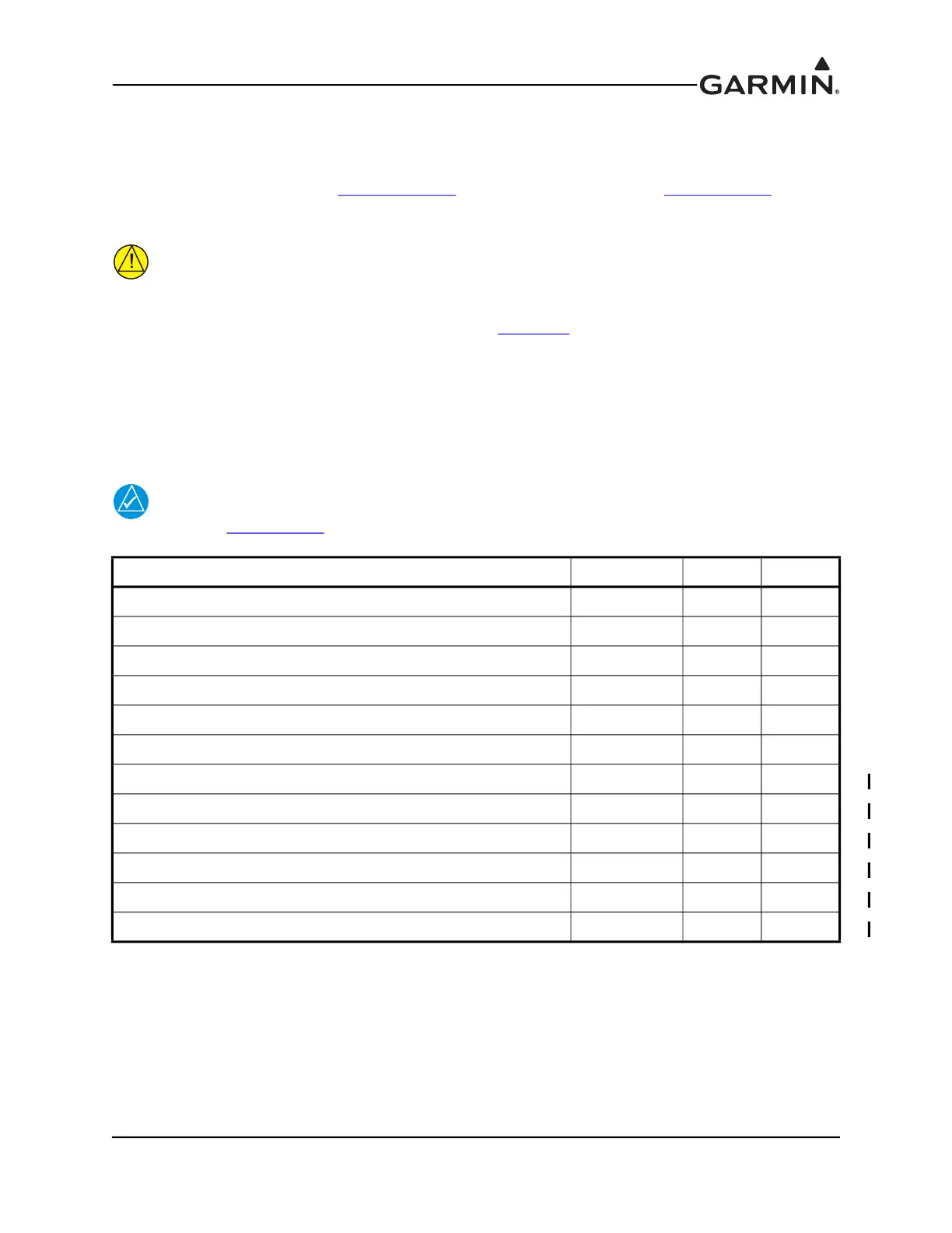
Pin Name Connector Pin I/O
FUEL QTY +5V_1 J244 5 Out
FUEL QTY 1 J244 6 In
FUEL QTY 1 GND J244 7 --
FUEL QTY +5V_2 J244 8 Out
FUEL QTY 2 J244 9 In
FUEL QTY 2 GND J244 10 --
GP 3 / FUEL QTY 3 HI / +5V 3 J244 11 Out
GP 3 / FUEL QTY 3 J244 12 In
GP 3 / FUEL QTY 3 LO / GND J244 13 --
GP 4 / FUEL QTY 4 HI / +5V 4 J244 14 Out
GP 4 / FUEL QTY 4 J244 15 In
GP 4 / FUEL QTY 4 LO / GND J244 16 --