190-01115-01 G3X™/G3X Touch™ Avionics Installation Manual
Rev. AV Page 30-210
30.4.32.25 Custom Analog Measurements
The GEA 24 and GSU 73 general purpose (GP) inputs allow the monitoring of installer-defined analog
parameters, which may be used for a variety of purposes. Selecting “Custom Analog” for a GPS input
allows the installer to enter up to 8 points of voltage-to-numeric calibration, as well as specifying the name
of the gauge
The values displayed for Custom Analog gauges are “unitless”, which allows the GP inputs to display a
calibrated value for any compatible analog voltage measurement. This includes O2 sensors, timing
advance, additional bus voltage inputs, additional bus current inputs and other applications with
compatible voltage levels. See pin description in Section 25
for allowable input voltage range.
NOTE
The GEA 24 GP 6 and GP 7 inputs require the LO side of the input to be connected to
ground. See Figure 26-2.2
for wiring details.
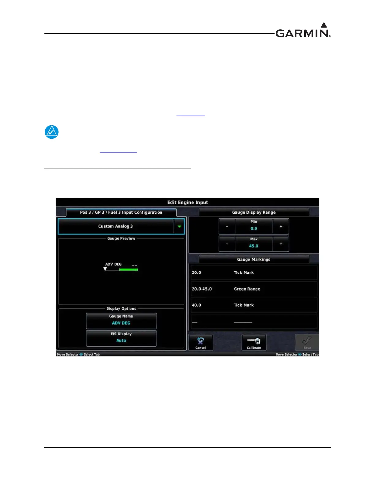
Example - Custom Electronic Ignition Advance Gauge
– The following two screenshots are an example of
an installer-defined engine gauge used to display the timing advance for an electronic ignition which
outputs 0.01 V/deg. In this example the gauge spans from 0 to 45 degrees of timing advance with tick
marks at 20 degrees and 40 degrees.