190-01115-01 G3X™/G3X Touch™ Avionics Installation Manual
Rev. AV Page 23-49
23.10 GMU 11 (Magnetometer)
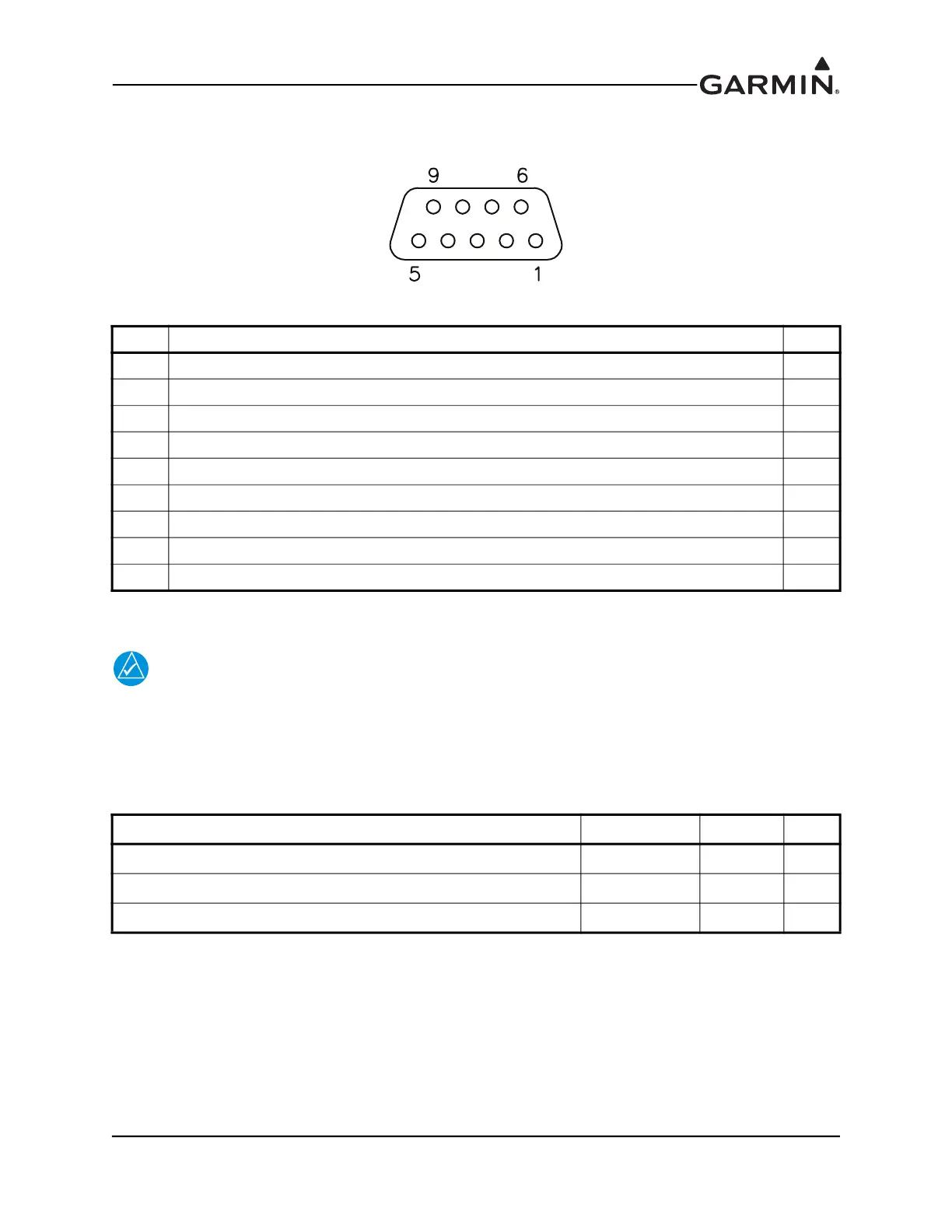
23.10.1 J441 Connector
Figure 23-21 J111 on GMU 11, as viewed looking at connector on unit
23.10.2 Power Function
NOTE
The GMU 11 must be powered from aircraft power. Do not connect the GMU 11 to the
magnetometer power output pins on the GSU 25 (these pins are intended for use only with
the GMU 22).
The GMU 11 is compatible with 14V and 28V systems. AIRCRAFT POWER 1 and
AIRCRAFT POWER 2 are “diode ORed” to provide power redundancy.
Pin Pin Name I/O
1 CAN BUS HI I/O
2 CAN BUS LO I/O
3 UNIT ID IN
4 RESERVED --
5 RESERVED --
6 SIGNAL GROUND --
7 AIRCRAFT POWER 1 IN
8 AIRCRAFT POWER 2 IN
9 POWER GROUND --
Pin Name Connector Pin I/O
AIRCRAFT POWER 1 J111 7 In
AIRCRAFT POWER 2 J111 8 In
POWER GROUND J111 9 --