190-01115-01 G3X™/G3X Touch™ Avionics Installation Manual
Rev. AV Page 20-3
It is the installer’s responsibility to make sure their choice of antenna meets FAA standards according to
the specific installation. This installation manual discusses only the antennas listed in Table 20-2
. Other
antennas may be acceptable but their installation is not covered by this manual.
There are several critical factors to take into consideration before installing an antenna for a satellite
communications system. These factors are addressed in the following sections.
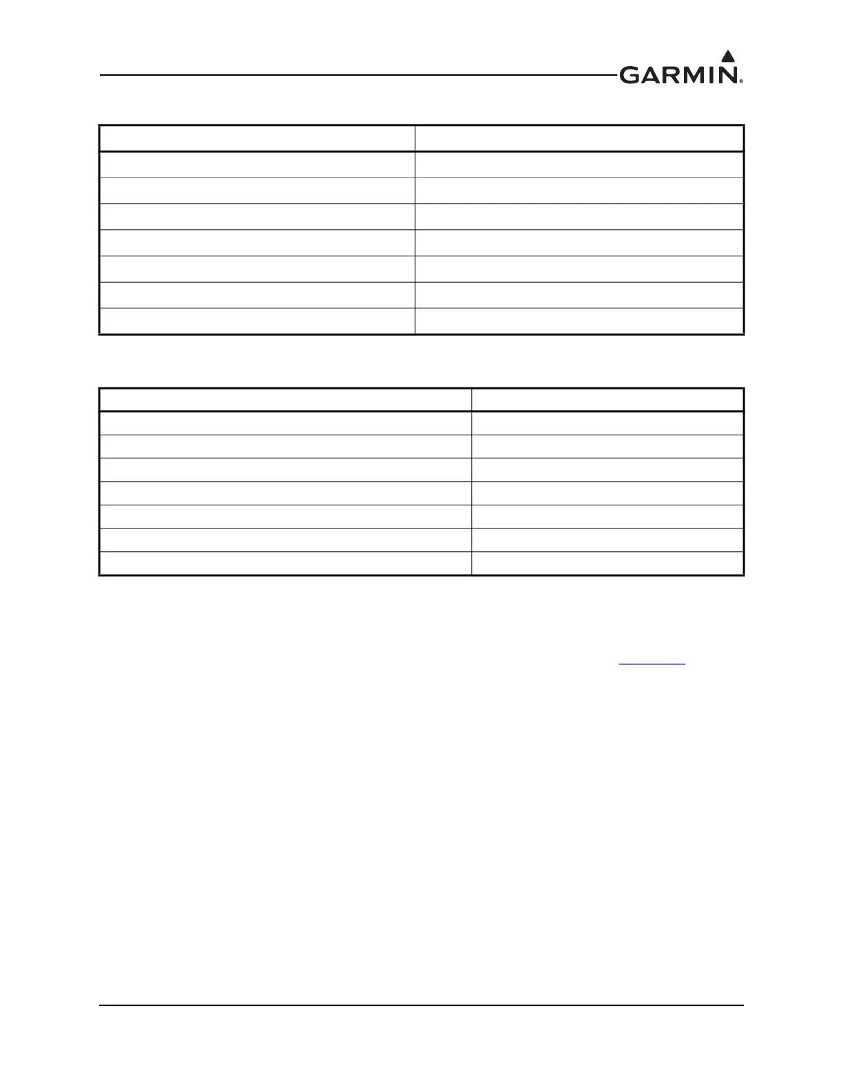
Table 20-3 GPS or GPS/WAAS Antenna Minimum Requirements
Characteristics Specifications
Frequency Range 1565 to 1585 MHz
Gain 16 to 25 dB typical, 40 dB max.
Noise Figure <4.00 dB
Nominal Output Impedance 50 Ω
Supply Voltage 4.5 to 5.5 VDC
Supply Current up to 50 mA
Output Connector BNC or TNC
Table 20-4 XM Satellite Radio Antenna Minimum Requirements
Characteristics Specifications
Frequency Range 2332.5 to 2345 MHz
Gain (Typical) 24 dB*
Noise Figure <1.2 dB
Nominal Output Impedance 50 Ω
Supply Voltage 3.6 to 5.5 VDC
Supply Current (maximum) 55 mA
Operating Temperature Gain -50 to +85° C
*For each 1 dB gain over 24 dB, add 1 dB of attenuation into the antenna cable path between the
antenna and the GDU.