190-01115-01 G3X™/G3X Touch™ Avionics Installation Manual
Rev. AV Page 30-136
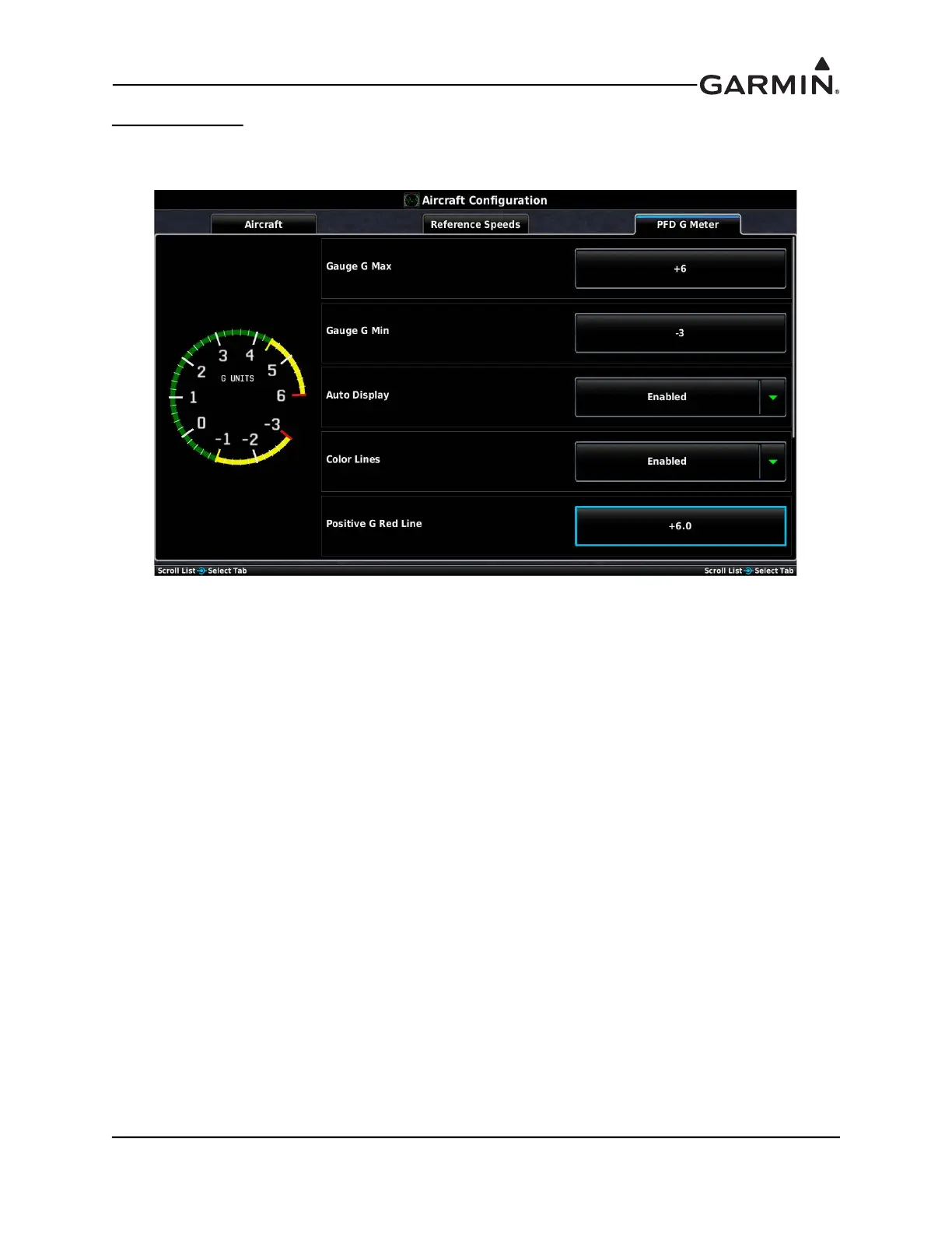
PFD G Meter Tab
The G-meter may be displayed at any time on the PFD Setup page. Not entering any values, or clearing the
values, disables the G-Meter entirely.
Gauge G Max–The Gauge G Max field allows for setting the maximum G values displayed on the PFD
G-meter.
Gauge G Min–The Gauge G Min field allows for setting the minimum G values displayed on the PFD
G-meter.
Auto Display–The Auto Display setting (On) allows the G-Meter to appear in place of the HSI when
G-loads on the aircraft exceed a fixed threshold (setting Auto Display to Off disables Auto Display of the
G-Meter)
Color Lines–When set to Enabled, this option allows the green, red, and yellow bands and the red and
yellow radial markings to appear on the G-Meter.
Positive G Red Line–This sets the point at which the red line appears for positive G values displayed on
the PFD G-meter.
Positive G Yellow Line–This sets the point at which the yellow line appears for positive G values
displayed on the PFD G-meter.
Negative G Yellow Line–This sets the point at which the yellow line appears for negative G values
displayed on the PFD G-meter.
Negative G Red Line–This sets the point at which the red line appears for negative G values displayed on
the PFD G-meter.