190-01115-01 G3X™/G3X Touch™ Avionics Installation Manual
Rev. AV Page 30-204
2. Position the control surface to match the trim position (up/left, neutral, down/right) displayed on
the calibration page, or position the flap to the desired position. Note that if the Flap Switch Mode
is configured for Absolute Position instead of Relative Position, the flaps will be moved by the
Flap Up/Flap Down buttons shown on the Flap Position Calibration page.
3. Note the resulting sensor value (in volts) displayed in the Sensor Value field (the sensor value
should change with each change in trim/flap position.
4. Press the Calibrate button to add a calibration point.
5. Press the Save button to store calibration data.
6. Repeat this process for each of the Trim/Flap Positions.
NOTE
Flap position values (up to 4 Absolute/8 Relative) should coincide with the angle of the
flap position as expressed in degrees (-90° – +90°) or percent (-100% to +100%).
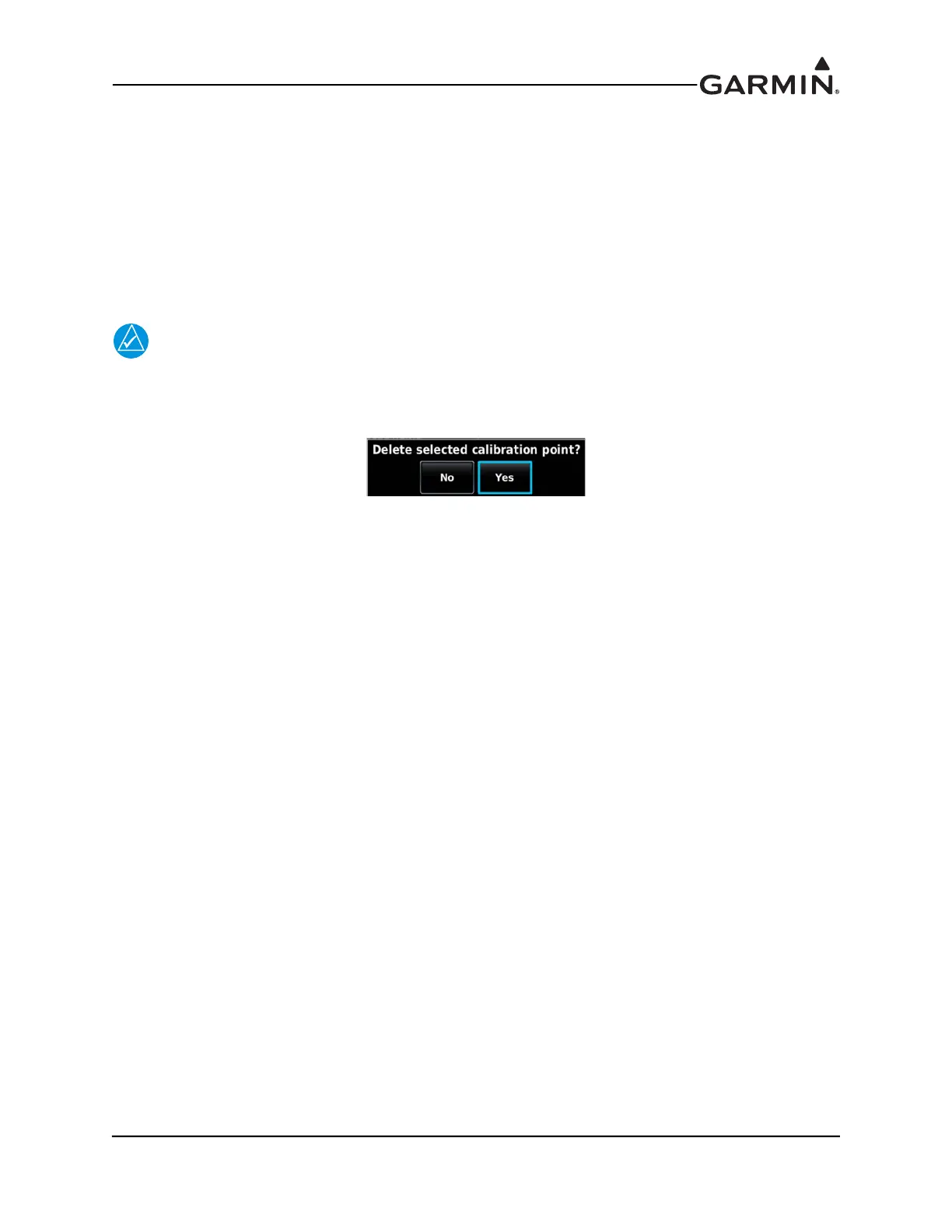
To delete a calibration value, highlight the desired data in the list, and press the Delete button.


 To Next Page