190-01115-01 G3X™/G3X Touch™ Avionics Installation Manual
Rev. AV Page A-2
3)
Set Initial Servo
Torque Limits
Autopilot tuning should be done with the maximum acceptable amount of servo
torque. The servo torque should be set to the maximum value that can still be
overpowered by the pilot in an emergency situation.
Set Initial Servo Torque Limits:
1. In configuration mode go to the Autopilot page
2. Set the “Max Torque” value for each servo to the maximum percentage
value that can still be overpowered by the pilot. Slowly apply force to the
stick in order to overpower the srrvo.
4)
Set Default
Autopilot Gains
The initial autopilot tuning should be done using the default gains settings.
Set All Initial Autopilot Gains to Default Value:
1. In configuration mode go to the Autopilot page
2. On The “Roll” tab, press the MENU button and hit the “Restore Default”
button to set Roll Servo gains to the default values
3. On The “Pitch” tab, press the MENU button and hit the “Restore Default”
button to set Pitch Servo gains to the default values
4. On The “Yaw Damper” tab, press the MENU button and hit the “Restore
Default” button to set Yaw Damper gains to the default values
5)
Enable Data
Logging on the
PFD Display
Data logging should be enabled so flight data and autopilot commands are logged
during flight. This data can later be analyzed to assist in autopilot tuning.
Enable Data Logging:
1. In configuration mode go to the Data Log page
2. Enable “SD Card Data Logging”
3. Place an SD card in the PFD card slot
6)
On Ground
Autopilot Test
Conduct an initial autopilot engagement and checkout with the aircraft on the
ground to verify proper control movement.
Engage AP and Verify Proper Control Movement
:
1. Engage AP in HDG/PIT mode
2. Move heading bug and verify proper aileron response
3. Move pitch reference and verify proper elevator response
4. Move aircraft nose back and forth and verify proper rudder response
5. Verify autopilot servos can be overpowered by the pilot by slowly
overpowering the servo torque
6. Verify autopilot disconnect functionality by pressing the AP Disconnect
button to disengage the autopilot.
7. If any of the above tests fail, refer to the “Servo Wiring Checkout” and
“Autopilot Setup” sections of the Installation Manual to correct these issues
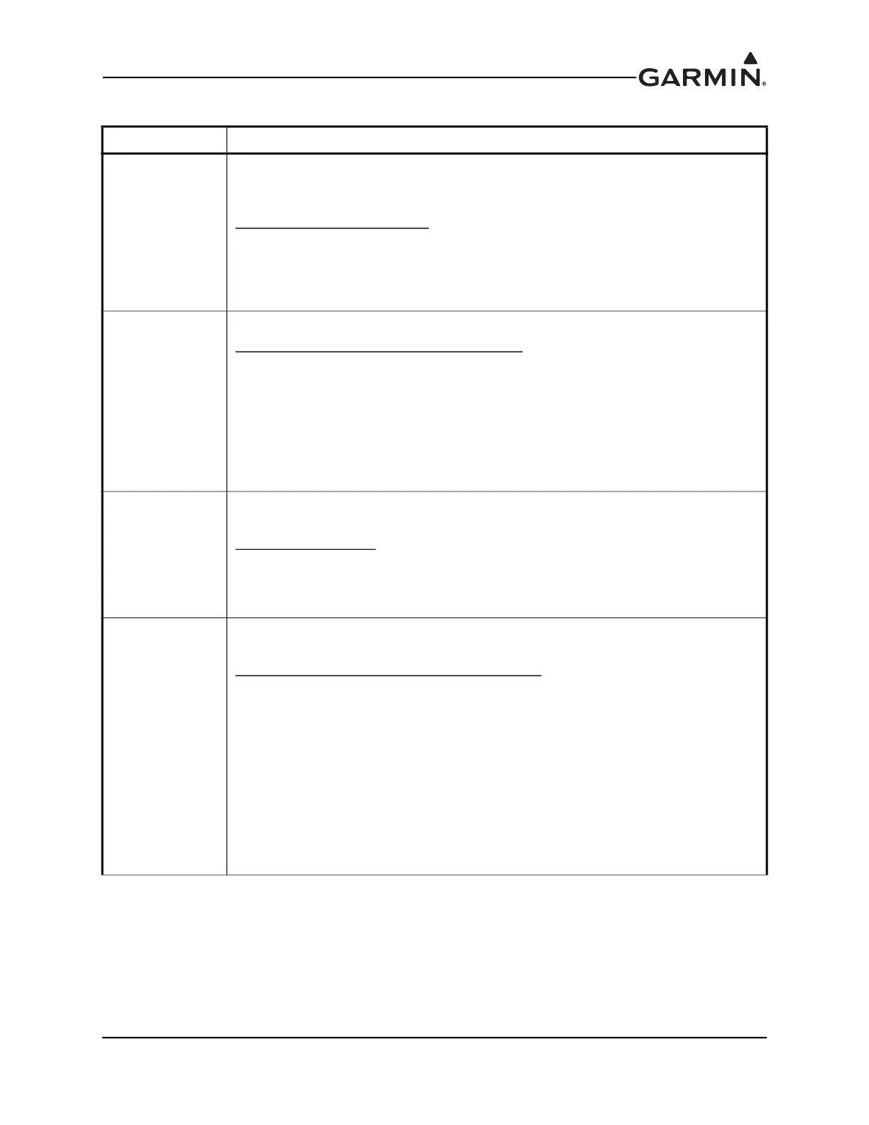
Table A-1 Flight Test Outline
Task Description