Chapter 9 Page no. 1134
JC-DR-A-190.fm
GE Healthcare Senographe DS
Revision 1 Service Information and Procedures Class A 2385072-16-8EN
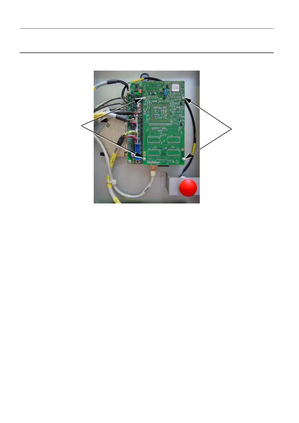
Job Card D/R A190 - Gantry CPU Board
To prevent damage to the connectors on the Interface Board, ensure that the top screws are progres-
sively tightened on each side.
4. Switch on the Gantry electrical power.
5. Wait until the Gantry boot is complete, and check that no error has been reported.
If the Gantry CPU board is operating correctly, the LED states are as follows:
• all three of the green LEDs in the upper part of the Gantry CPU board (i.e. DS1, DS2, and DS3)
are ON
• the first eight of the block of yellow LEDs starting on the left (i.e. DS4, DS5, DS6, DS7, DS8, DS9,
DS10, and DS11) blink in a cycling fashion from outside to inside
• the last two of the block of yellow LEDs on the right-hand side (i.e. DS12 and DS13) are OFF
6. Switch off the Senographe electrical power.
7. Lift the top metal panel up to release it from the left side of the framework. Put it back over the frame-
work to hide the newly installed Gantry CPU board.
8. Reinstall the column cover (CPU side); refer to Job Card PHY A044 - Remove/Reinstall Gantry Cov-
ers on page 523.
2
2

 Loading...


