GE Healthcare Senographe DS
Revision 1 Service Information and Procedures Class A 2385072-16-8EN
Job Card D/R A232 - Lift Screw Assembly
Page no. 1263 Chapter 9
JC-DR-A-232.fm
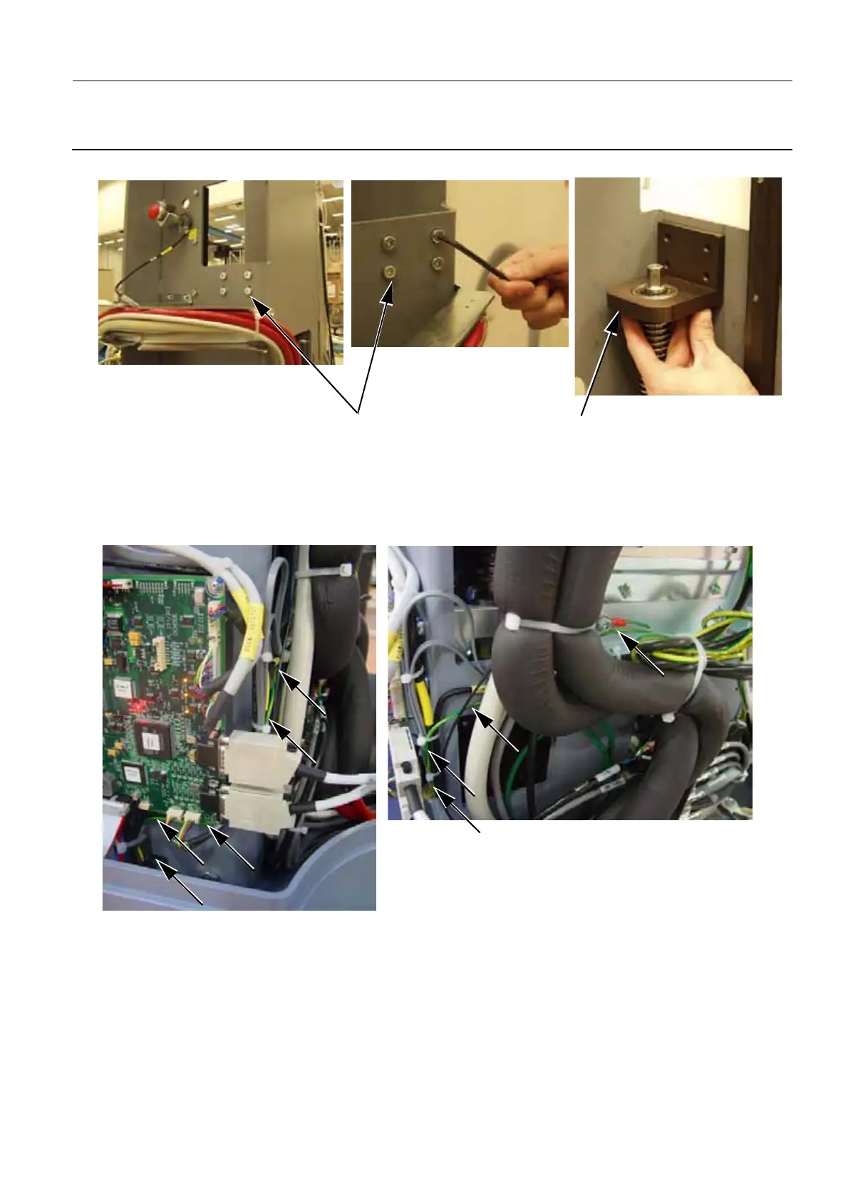
10. Release the screws (11) of Upper L-Shape Bearing Housing (12) (5 mm allen wrench) and remove it.
11. Power off the Gantry.
12. If you are changing a Type 2 Lift Screw Assembly, disconnect the earth cable that is routed to the
bottom left corner of the Detector Power Supply plate. If theType 2 Lift Screw Assembly also has the
Top Brake installed, remove the Top Brake cable from the J6 connector on the Lift Board.
If you are changing a Type 3 Lift Screw Assembly, disconnect the earth cable that is routed to the
bottom left corner of the Detector Power Supply plate and disconnect the Motor Brake cable that is
connected to the J6 connector on the Lift Board.
13. Remove the Lift Board (refer to Job Card D/R A201 - Lift Board on page 1161). This exposes the
screws that connect the lower part (Bearing Block) of the Lift Screw Assembly to the Gantry frame.
14. When you remove the Lift Board, route the cables (13) from the DC motor though the side of the
11
12

 Loading...


