Chapter 9 Page no. 1284
JC-DR-A-233.fm
GE Healthcare Senographe DS
Revision 1 Service Information and Procedures Class A 2385072-16-8EN
Job Card D/R A233 - Lift Screw Assembly Top Brake
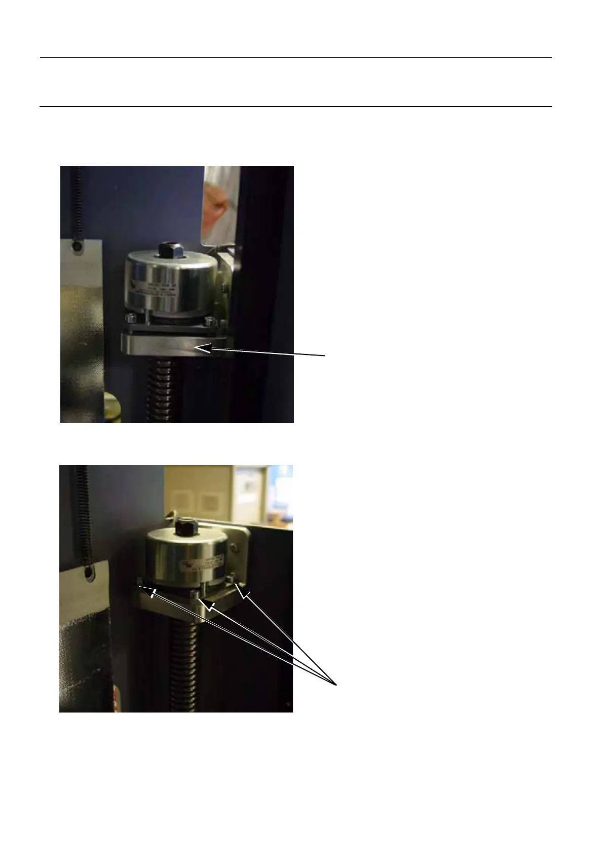
3. Lower the Lift screw Assembly Top Brake (2) down on to the top of the Lift screw Assembly, and
ensure that the holes (4) in the Lift screw Assembly Top Brake align with the threaded holes of the
bracket (5). You may need to move the Lift Screw Assembly Top Brake until each side is flush to the
bracket.
4. Secure the Lift Screw Assembly Top Brake to the bracket with the four allen screws (6) (4 mm allen
wrench). Progressively tighten the opposite corners together so that equal pressure is applied to the
fixations between the bracket and the Lift Screw Assembly Top Brake.
5. Connect the Lift screw Assembly Top Brake cable (W510) to the J6 connector on the Lift Board, and
5
6

 Loading...


