Chapter 9 Page no. 1292
JC-DR-A-243.fm
GE Healthcare Senographe DS
Revision 1 Service Information and Procedures Class A 2385072-16-8EN
Job Card D/R A243 - Compression Potentiometer and Cable
6-2 Installation of the New Potentiometer
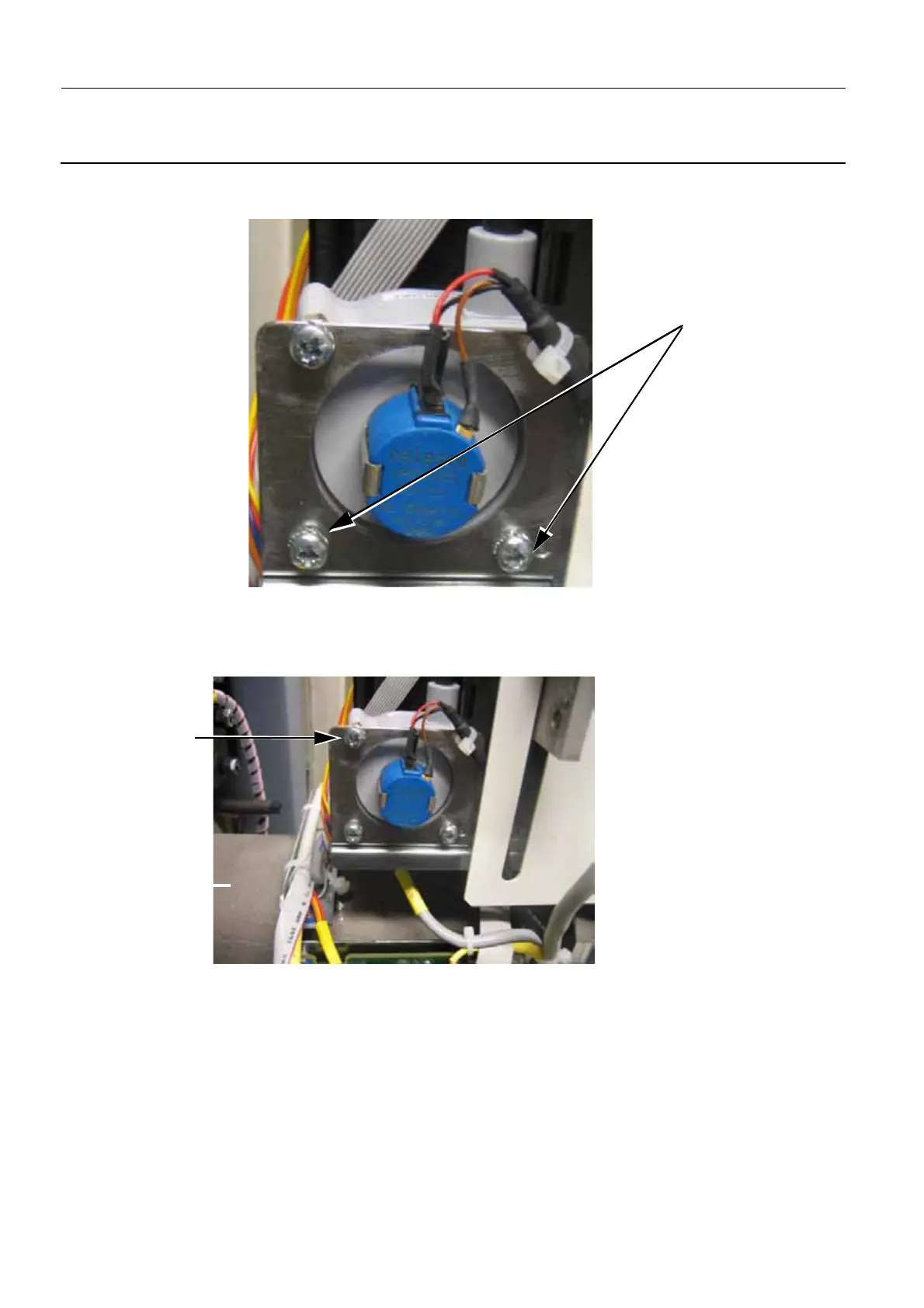
1. Remove the lower two of the three Compression Potentiometer Support screws (1).
2. Loosen the remaining third screw on the left upper corner of the Compression Potentiometer Sup-
port. This allows inserting the Compression Potentiometer Support attachment screws.
Note:
Do not remove the upper left screw (2), only loosen it slightly.
3. Place the Compression Potentiometer and its Support (with the remaining loose screw) on the Com-
pression Assembly frame and insert and tighten the two M4 Allen screws (3) (3 mm Allen wrench) to
attach the Support to the Compression Assembly frame. When attaching the Support, ensure you
use the correct holes on the Support in order to align the potentiometer wire vertically. Apply Loctite
1
2

 Loading...


