GE Healthcare Senographe DS
Revision 1 Service Information and Procedures Class A 2385072-16-8EN
Job Card D/R A246 - Manual Compression Brake
Page no. 1303 Chapter 9
JC-DR-A-246.fm
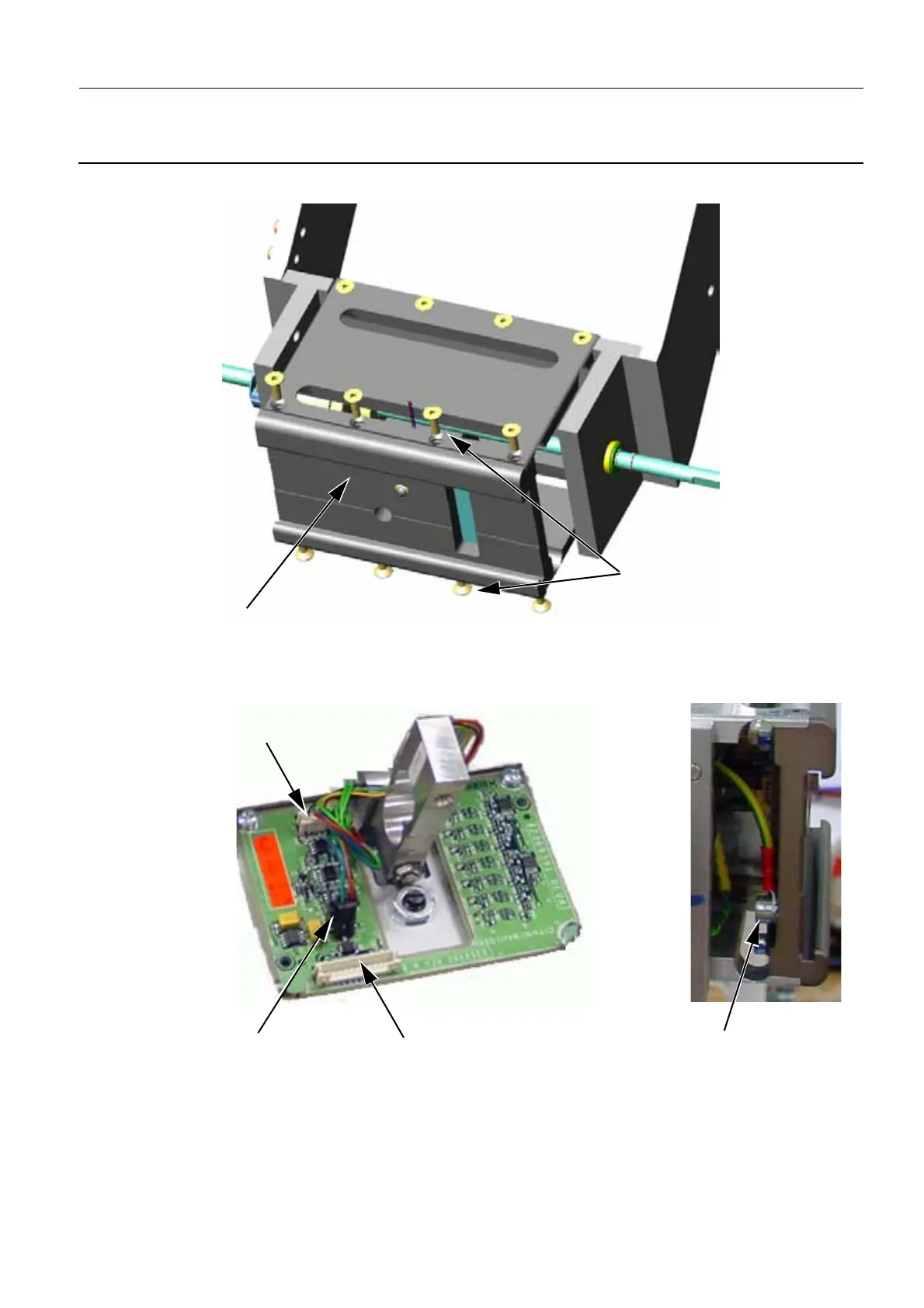
Holder (4) being sure not to brake the cables connected to the Paddle Holder board.
4. On the Paddle Holder board, carefully disconnect the Paddle Recognition cable from the J2 connec-
tor, Force Sensor cable from the J1 connector and Motor cable from the J2 connector. Disconnect
the ground cable from the Paddle Holder.
5. Remove the four pairs of M4 screws (5) (3 mm allen wrench), and then remove the upper and lower
4
3
J2 : Paddle Recognition Cable
J1 : Force Sensor
J3 : Manual Compression Brake
(J1 / PL304 - W304)
(J3 / PL304 - W314)
(J2 / PL304 - W319)
Paddle Holder
Earth Cable

 Loading...


