GE Healthcare Senographe DS
Revision 1 Service Information and Procedures Class A 2385072-16-8EN
Job Card D/R A247 - Motorized Compression Brake
Page no. 1311 Chapter 9
JC-DR-A-247.fm
4. Switch on the power because the brake must be
supplied with continuous current for removal.
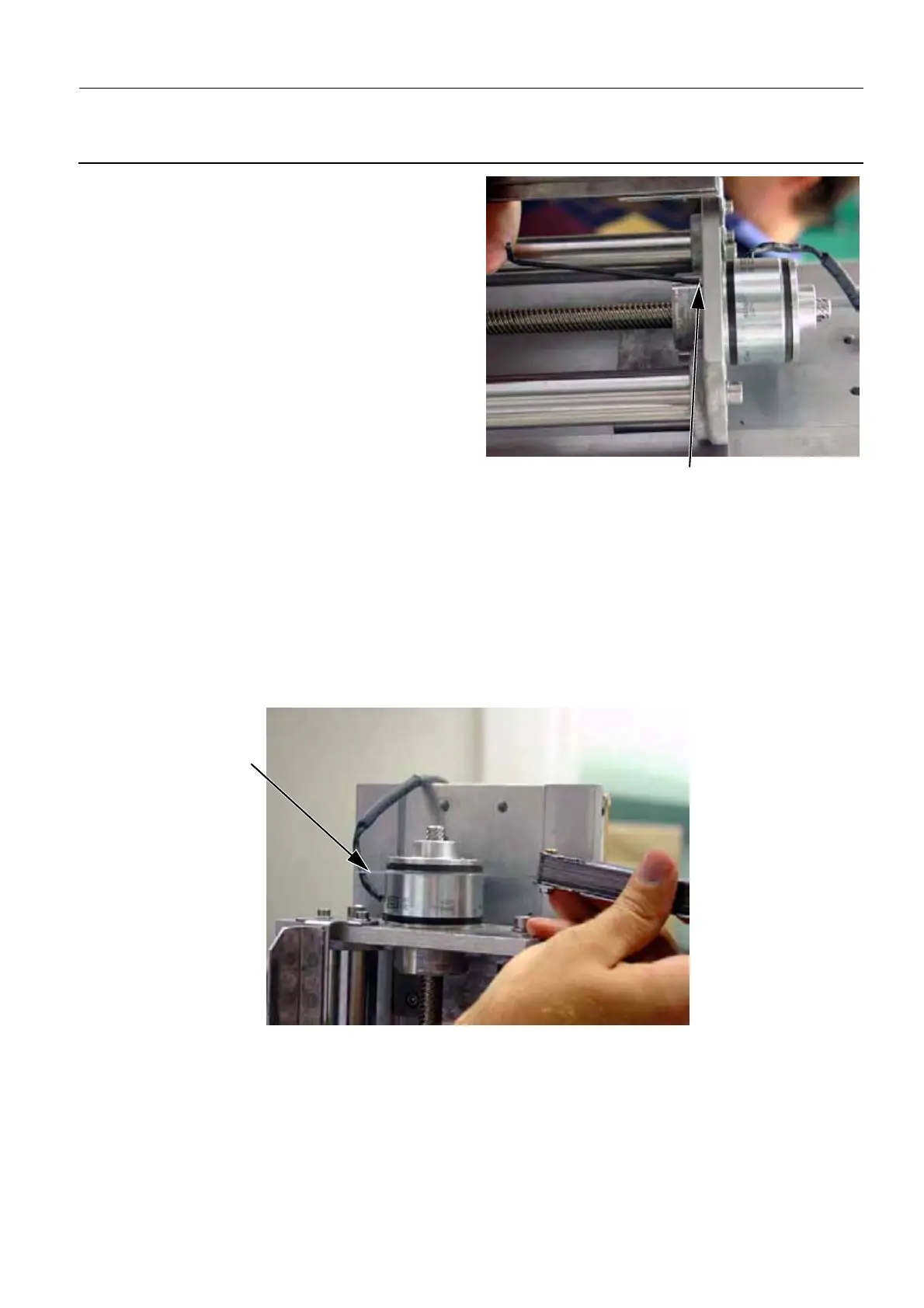
5. The brake is now free. Release the three screws
(5) securing the motorized compression brake
(2.5 mm allen wrench) and remove it gently to
avoid losing the key (6).
6. Disconnect the power cable (W309) from the Arm
Distribution Board (connector J5).
6-2 Reassembly of the Motorized Com-
pression Brake
• Reverse the disassembly procedure
Remember to reconnect the brake supply cable W309 to J5 on the Compression Board and W307 to
the Arm Distribution Board.
Add the following steps when reassembling the motorized compression brake:
Note:
The brake must be supplied with continuous current for installation.
• Insert a 0.2 mm feeler gauge (7) as shown in the following illustration:
• Apply blue Loctite to the threads of the three screws securing the brake before tightening them.
5
6

 Loading...


