Chapter 9 Page no. 1526
JC-DR-A-331.fm
GE Healthcare Senographe DS
Revision 1 Service Information and Procedures Class A 2385072-16-8EN
Job Card D/R A331 - UPS
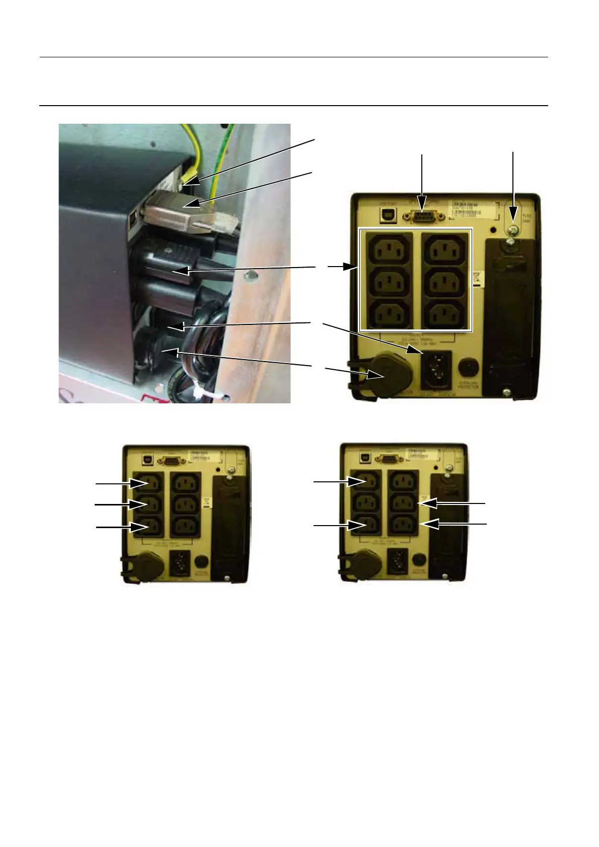
3. Connect the ground cable (3) (small screwdriver) to the TVSS GND connector of the UPS rear panel.
4. Connect all the power cables (4) from the Control Station Components to the power output sockets
on the UPS rear panel, as indicated below:
5. Connect the AC mains supply power cable (5) from to Generator to the power input socket on the
UPS rear panel.
6. Connect the communications cable (6) to the UPS Monitor Port connector of the UPS rear panel.
3
6
7
5
4
3
6
IDC
AC Multi-
ADS
Socket
IDC
ADS
Pre-Penduick V3 Control Stations
Penduick and above V3 Control Stations
Switch
Monitor
and V4 Control Stations

 Loading...


