Chapter 9 Page no. 1544
JC-DR-A-401.fm
GE Healthcare Senographe DS
Revision 1 Service Information and Procedures Class A 2385072-16-8EN
Job Card D/R A401 - Generator CPU Board 400PL3
6 PROCEDURE
6-1 Remove Existing EEPROMs
Remove the existing EEPROMs from the Generator Board CPU as explained insection 7-1, Remove the
Existing EEPROMs on the Generator CPU Board on page 1627 in Job Card D/R A415 - Generator
Board CPU EEPROMs.
6-2 Removing the Original Generator CPU Board
1. Switch off the electrical power supply from the Mains Distribution Panel in the room. Apply an appro-
priate LOTO padlock and label. Wait 10 minutes for the components within the Generator to dis-
charge.
2. Remove the Generator front panel (CPU side) to reveal the Generator CPU board 400PL3; refer to
Job Card PHY A042 - Remove/Reinstall Generator Covers on page 513.
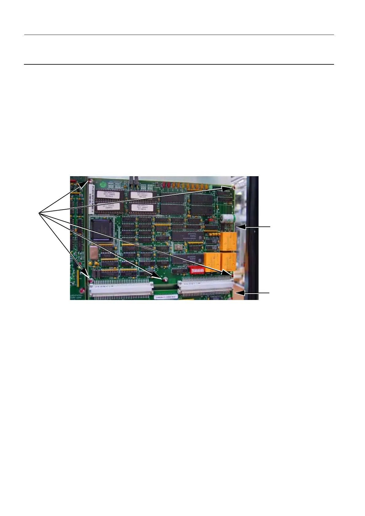
3. Remove the five screws (1) (4 mm allen wrench) that secure the Generator CPU board 400PL3 to
the Generator cabinet.
4. Gently pull and forwards the Generator CPU board 400PL3 to remove it from the two gray connec-
tors (2) on the Generator Command board.
6-3 Installing the New Generator CPU Board
1. Carefully push the new Generator CPU board 400PL3 in to the two gray connectors (1) on the Gen-
erator Command board. Ensure that the connections on the two gray connectors are fully secure and
1
Generator
CPU Board
Generator
Control Board
2
2

 Loading...


