GE Healthcare Senographe DS
Revision 1 Service Information and Procedures Class A 2385072-16-8EN
Job Card D/R A415 - Generator Board CPU EEPROMs
Page no. 1627 Chapter 9
JC-DR-A-415.fm
7 PROCEDURE
7-1 Remove the Existing EEPROMs on the Generator CPU Board
1. Switch off the electrical power supply from the Mains Distribution Panel in the room. Apply an appro-
priate LOTO padlock and label and open the circuit breaker at the bottom part of the Generator. Wait
10 minutes for the components within the Generator to discharge.
2. Remove the Generator front panel (CPU side) to reveal the Generator CPU board 400PL3; refer to
Job Card PHY A042 - Remove/Reinstall Generator Covers on page 513.
3. With the EEPROM removal tool, on the Generator CPU board taking care of components around,
remove slowly the four EEPROMs B43, B44, B48 and B49.
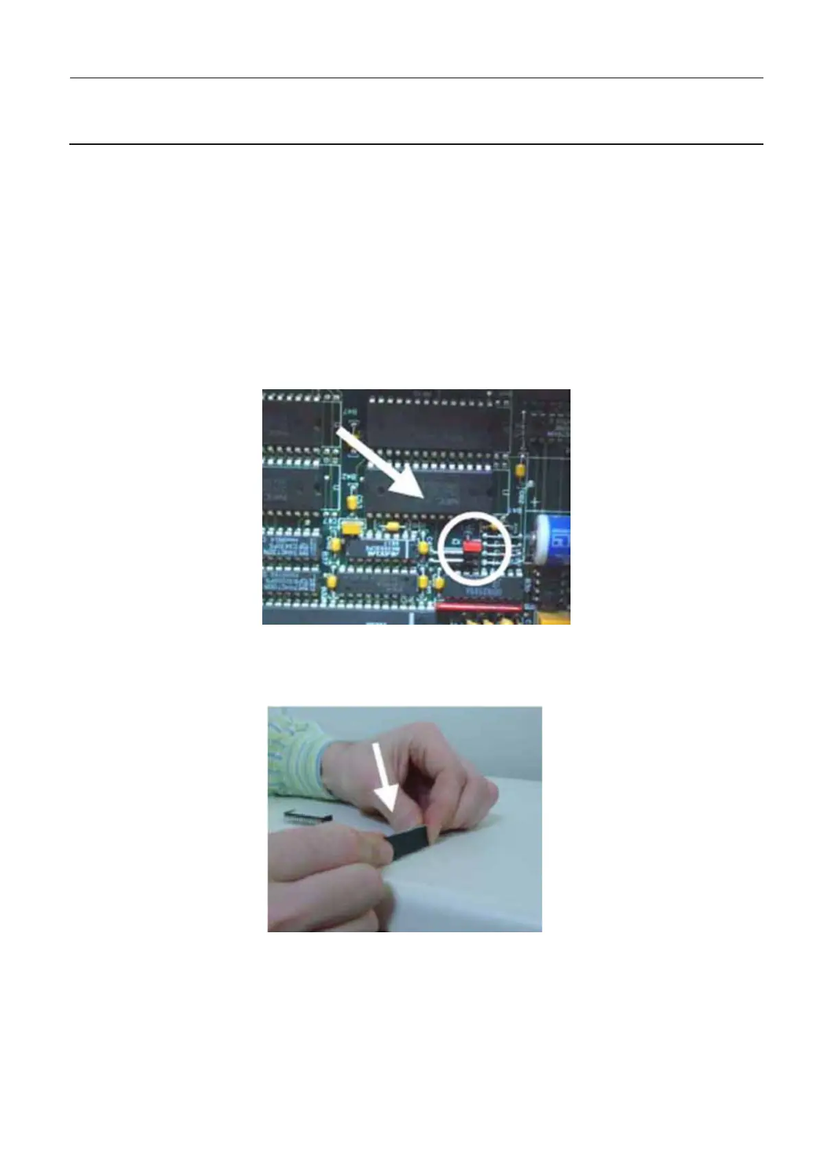
4. Remove the X2 jumper for 10 seconds and plug it back into the X2 pins again in horizontal position.
This action erases the NV RAM content.
7-2 Install New EEPROMs on the Generator CPU Board
New PROMs may have pins set too far apart. Tighten them smoothly, as shown below.
1. Taking care not to damage the pins of the EEPROMs, insert the four new EEPROMs into the new
generator CPU board. Refer to Table 1 on page 1628 and to Illustration 1 on page 1629 to identify
the applicable EEPROMs and the sockets into which they must be inserted:

 Loading...


