Chapter 3 Page no. 242
Indicators and Switches.fm
GE Healthcare Senographe DS
Revision 1 Service Information and Procedures Class A 2385072-16-8EN
Central Listing
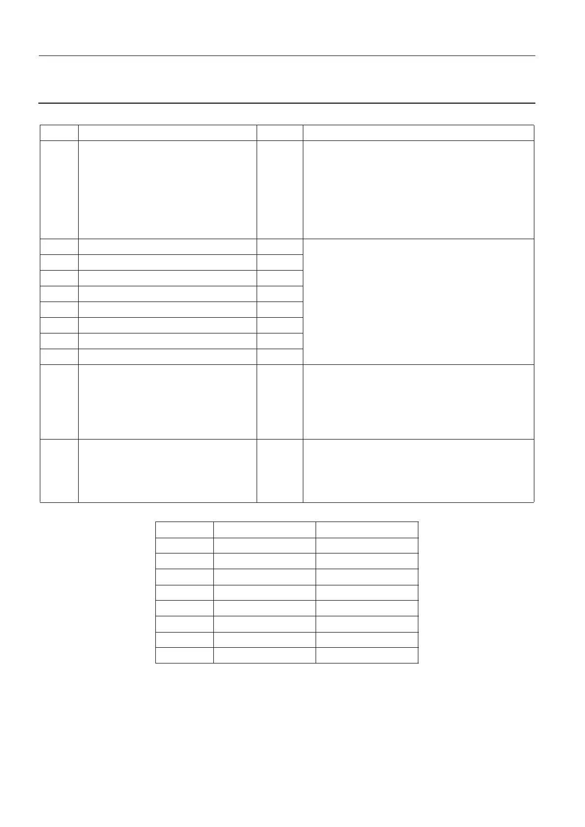
2-1-4. Generator CPU Board 400PL3 LEDs
2-1-5. Generator CPU Board 400PL3 B1 Switches
LED Function Color Behavior
DS1 Test OK Green Normal status: ON
ON when the Generator CPU Board has under-
taken its self-test successfully and is operating nor-
mally.
OFF when the Generator CPU Board has failed its
self-test and is not operating normally.
DS2 Tx TTL B1 Yellow Communication signals
Normal status: ON/OFF/Blinking
ON/Blinking when the Generator CPU board is
sending/receiving communication data.
OFF when the Generator CPU board is not send-
ing/receiving communication data.
DS3 Rx D B1 Yellow
DS4 Tx TTL A2 Yellow
DS5 Rx D A1 Yellow
DS6 Tx TTL A2 Yellow
DS7 Rx D A2 Yellow
DS8 Tx TTL B2 Yellow
DS9 Rx D B2 Yellow
DS10 Halt Red Normal status: OFF
ON when the Generator CPU Board is in the halt
state.
OFF when the Generator CPU Board is operating
normally.
DS11 Reset Red Normal status: OFF
ON when the Generator CPU Board is being reset.
OFF when the Generator CPU Board is operating
normally.
Switch Function Default Position
1N.C Open
2N.C Open
3IN5 Open
4IN4 Open
5IN3 Open
6IN2 Open
7IN1 Open
8 IN0 Closed

 Loading...


