Chapter 3 Page no. 264
Indicators and Switches.fm
GE Healthcare Senographe DS
Revision 1 Service Information and Procedures Class A 2385072-16-8EN
Central Listing
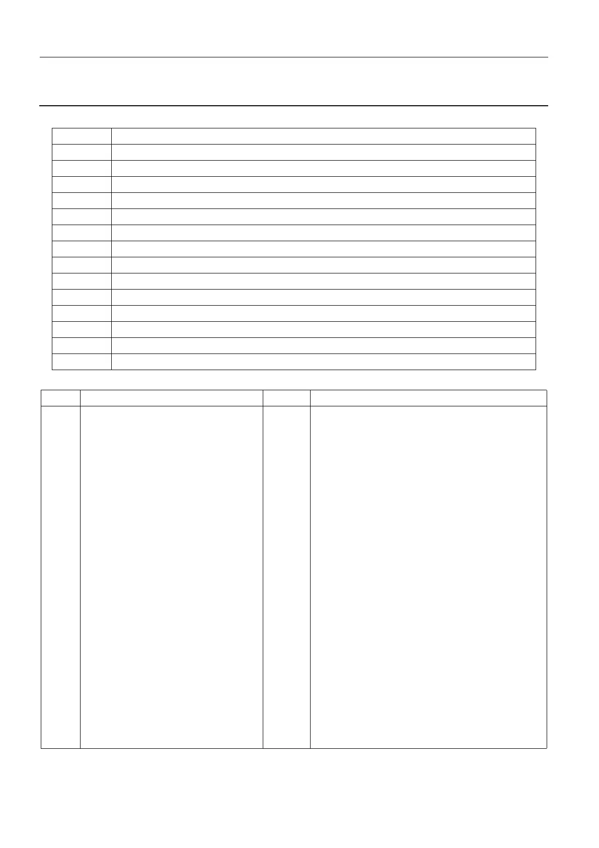
2-6-1. Mains Distribution Board 200PL1 Connectors
2-6-2. Mains Distribution Board 200PL1 LEDs
Connector Function
XJ1 PH1
XJ2 SEL
XJ3 N/PH2
XJ4 W2
XJ5 Not Applicable
XJ6 300 VR
XJ7 W1
XJ8 600 VF
XJ9 0V (-600V)
XJ10 To Relay K1
XJ11 To the XJ2 connector on the Supply Command Board 200PL2 (+12V, control/data signals)
XJ12 Seno ON
XJ13 X-ray ON
XJ14 Seno ON/X-ray ON
LED Function Color Behavior
DE1 Attente MST Red Normal status: OFF
ON when the DC Bus is below a level of 30 V. Usu-
ally ON for a few seconds after the X-ray Console
ON button is pressed while the DC Bus reaches
30 V.
If permanently ON, there is a problem with the DC
Bus reaching 30 V. In this case, proceed as follows:
• Check the status of the DC Bus indicated by yel-
low DE5 LED.
• If the DE5 LED is ON there is a problem with the
Mains Distribution Board 200PL1, and you must
change it.
• If the DE5 LED is OFF there is a problem with the
600 V on the Inverter Board 300PL1. Check
200PL1 XJ8 and 300PL1 X5 connectors - if the
connectors are OK change 300PL1.
If the DE1 LED on the Mains Distribution Board
200PL1 and the DE2 LED on the Supply Command
Board 200PL2 are not the same state, change the
cable between the XJ11 connector on the Mains
Distribution Board 200PL1 and the XJ2 connector
on the Supply Command Board 200PL2.
OFF when the DC Bus is operating normally at a
level of around 600 V.