Chapter 3 Page no. 320
Cables.FM
GE Healthcare Senographe DS
Revision 1 Service Information and Procedures Class A 2385072-16-8EN
Cable Lay-out and Pin-out
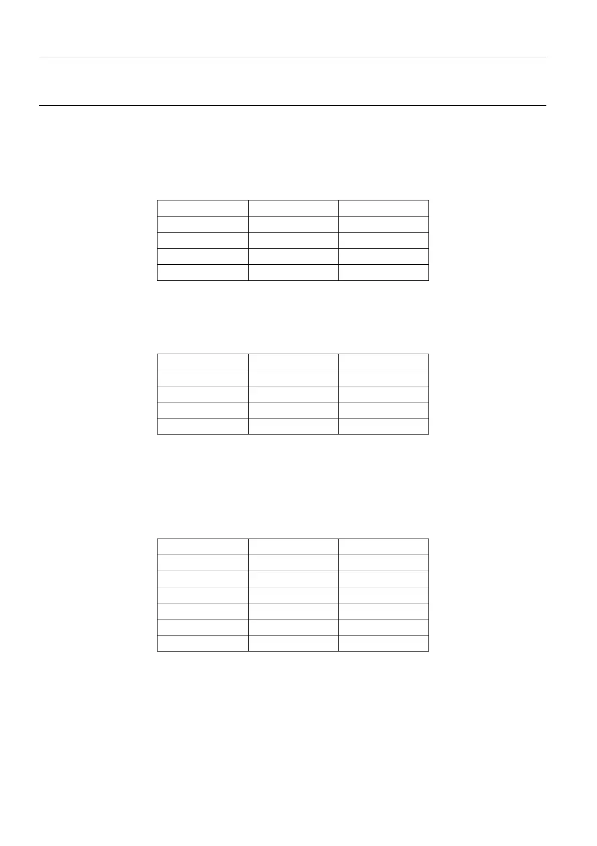
1-84. W504 – Rectangular Blade Optical Sensor Connect
Four cables used to connect the rectangular blade optical sensor connectors (S1 through S4) to the
Interconnection board connectors S1 through S4.
Connectors Sx in the table below correspond to the following:
- Front blade - S1; Left blade - S2; Rear blade - S3; Right blade - S4:
1-85. W505 – Filter Wheel Optical Sensor Connect
Filter Wheel optical sensor (S5) to Interconnection board S5:
1-86. W506 – Rectangular Blade DC Motor Connect
Four cables, used to connect the rectangular blade DC motor connectors (M1 through M4) to the Inter-
connection board connectors M1 through M4 (board PI 2376693).
Connectors Mx in the table below correspond to the following:
- Front blade - M1; Left blade - M2; Rear blade - M3; Right blade - M4:
Designation Level Pin No.
VCC 5 V Sx-1
LED-K 0/1.3 V Sx-2
GND 0 V Sx-3
Zero 0/5 V Sx-4
Designation Level Pin No.
VCC 5 V S5-1
LED-K 0/1.3 V S5-2
GND 0 V S5-3
Zero 0/5 V S5-4
Designation Level Pin No.
Motor - 0/24 V Mx-1
Motor + 0/24 V Mx-2
GND 0 V Mx-3
VCC 5 V Mx-4
Channel B 0/5 V Mx-5
Channel A 0/5 V Mx-6
 Loading...


