Chapter 6 Page no. 456
JC-PHY-A-014.fm
GE Healthcare Senographe DS
Revision 1 Service Information and Procedures Class A 2385072-16-8EN
Job Card PHY A014 - Connect Gantry to Control Station
6-2 Connecting Cables Coming from the Harness
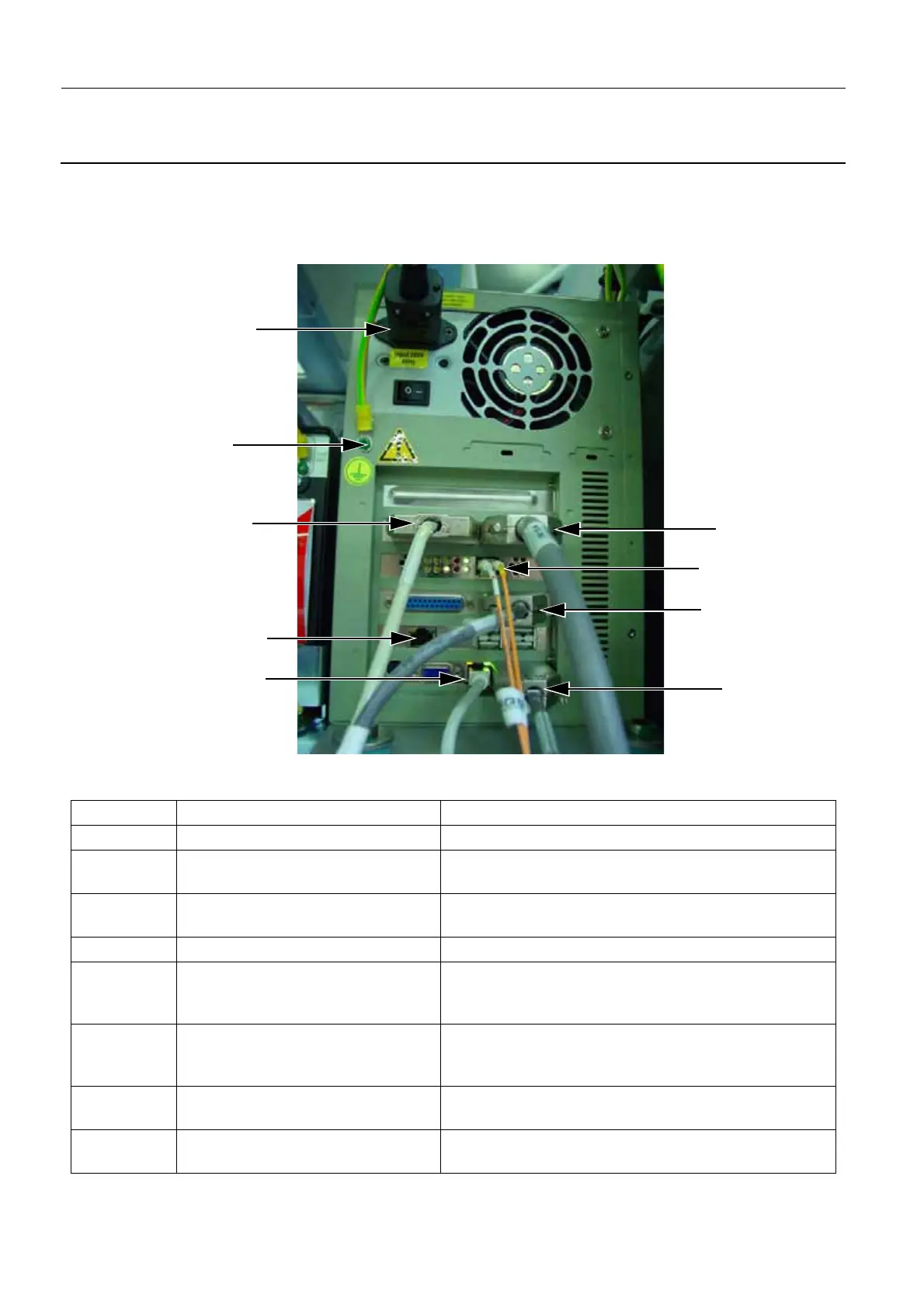
You must connect cables from the harness to the IDC, ADS, UPS, and Ethernet switch as follows:
1. Connect the cables from the harness to the IDC as specified below in the illustration and table. The
power and ground cables, and the gray Ethernet cable to the ADS should already be connected.
Reference Cable Label Cable Description/Location
1 IDC-SIB 2244615 IDC - Gantry Serial Link RT (1) to 50-pin connector
2 IDC-COM1 2226612 IDC - Gantry Conditioner Link to
top right 9-pin COM1 connector
3 IDC-SIB 2226621 IDC - Detector Power Supply to
26-pin connector
4 IDC-COM2 2244615 IDC - Gantry Serial Link RT to COM2 9-pin connector
5 2389288-2 IDC - ADS link via router.
Grey 100 Mbit/s Ethernet cable to RJ-45 connector.
This should already be connected.
6 IDC I/O 2340426 IDC - Detector link. Two fiber optic cables to fiber optic
connectors. Fiber labelled A (white) on the left, yellow
on the right.
7 None - Power Cable Power connector from UPS. This should already be
connected.
8 None - Earth Cable Earth cable from earth bar. This should already be con-
nected.
2
3
1
7
6
4
Note: An empty Ethernet port exists to the left hand side of the USB ports. The Ethernet cable from the switch must be connected to the lowest
Ethernet port, which is to the left hand side of the IDC - Gantry Conditioner Link.
5
Empty
8

 Loading...


