Chapter 7 Page no. 566
JC-ELE-A-010.fm
GE Healthcare Senographe DS
Revision 1 Service Information and Procedures Class A 2385072-16-8EN
Job Card ELE A010 - Set Lift Travel Limits
The numbered circles 1, 2, 3 and 4 correspond to the procedural sections within this Job Card as follows:
1. 6-2-1, Upper Optical Fork Positioning
2. 6-2-2, Lower Limit Adjustment (Lift Potentiometer Lower Reference Voltage at 0 mm)
3. 6-2-3, Upper Limit Adjustment (Lift Potentiometer Upper Reference Voltage at 650 mm)
4. 6-2-4, Selection of the Lift Travel Limit (Completion)
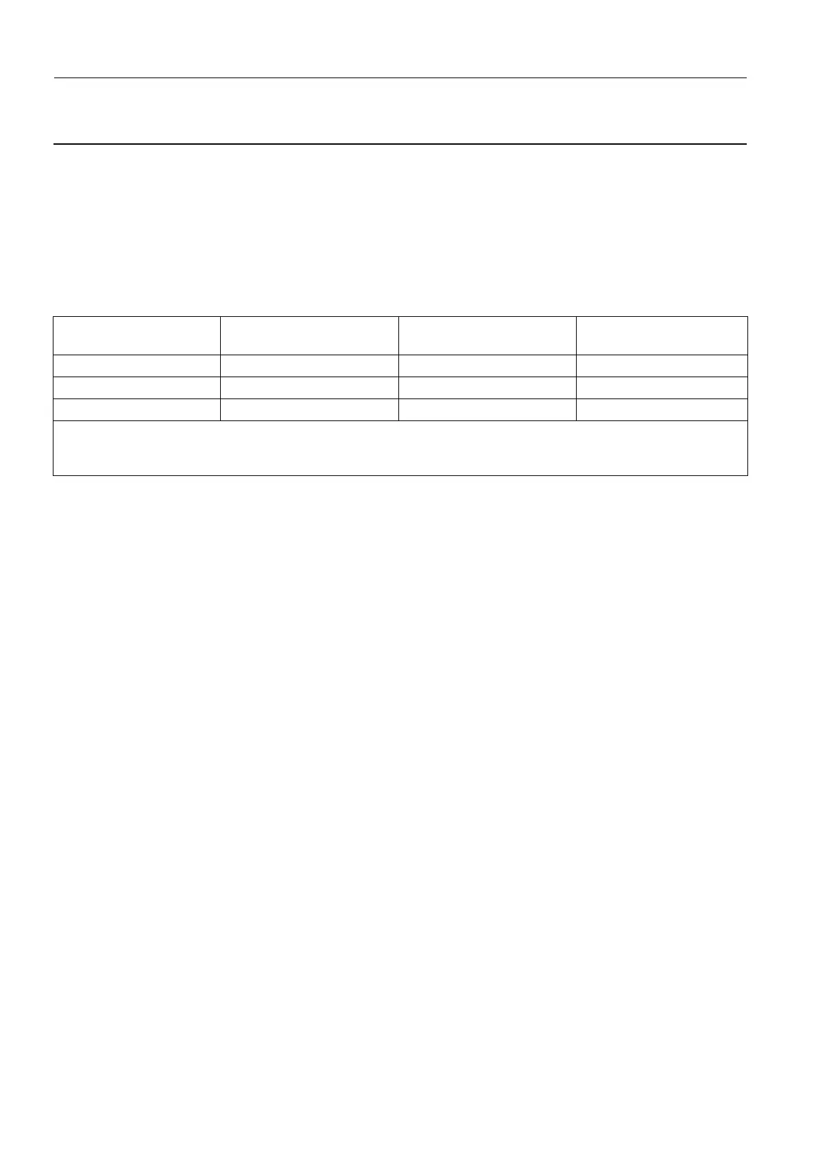
The top of the Senographe system Tube Head can travel up to three discrete maximum heights, corre-
sponding to each of the three different lift travel limits. The maximum Tube Head heights and minimum
required ceiling corresponding to each of the three different Lift Travel Limits, are as follows.
Note:
The information in the table above assumes that you have accurately set the lower lift travel limit
to 670 ±2 mm from the floor.
Goal of Calibration:
• Select the upper optical fork position to avoid collision with the ceiling.
• Calibrate the Lift Potentiometer.
• Set the lift lower limit and the lift travel limit in software, defining the minimum and maximum usable
heights.
Lift Travel Limit Corresponding Upper
Optical Fork Position
Corresponding Max.
Tube Head Height *
Recommended Min.
Ceiling Height **
650 mm Bottom 2230 mm 2300 mm
750 mm Middle 2330 mm 2400 mm
850 mm (default setting) Top (default setting) 2430 mm 2500 mm
* - Assumes that the lower lift travel limit is accurately set.
** - The recommended minimum ceiling height assumes that there is a marginal gap of 70 mm between the top of
the Tube Head and the ceiling.