Chapter 9 Page no. 972
JC-DIAG-A-1000.fm
GE Healthcare Senographe DS
Revision 1 Service Information and Procedures Class A 2385072-16-8EN
Job Card DIAG A1000 - Gantry Diagnostic
Recommended Actions
1. Ensure that the Generator is powered on.
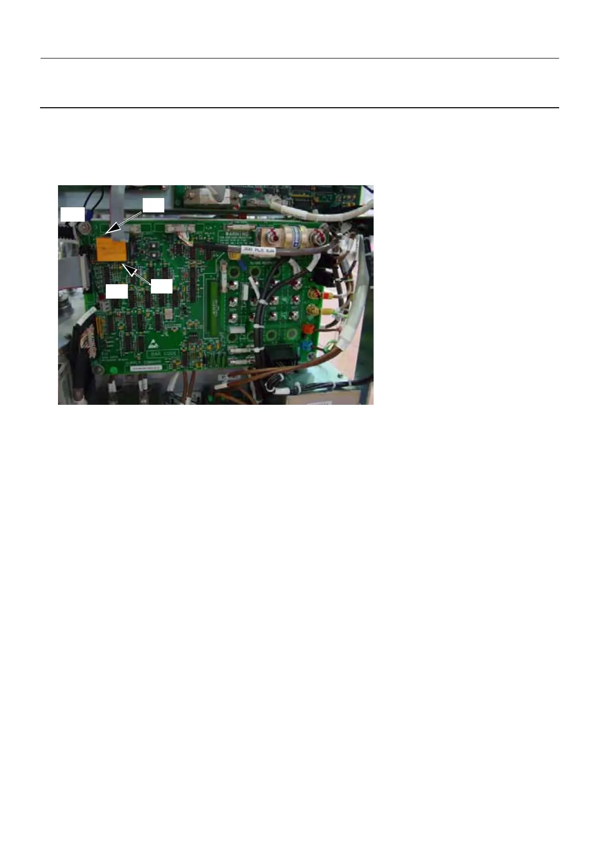
2. If the problem persists, use a multimeter to check the voltage between the TP10 connector and the
top left bolt earth point on Generator Supply Command board. The expected voltage when the W125
cable connections are firmly in place is 9.2 V ± 0.5 Vdc.
• If the voltage between the TP10 connector and the earth point on the Generator Supply Com-
mand board is 9.2 V ± 0.5 V dc, change the PDU board according to Job Card D/R A191 - PDU
Board on page 1137.
• If the voltage between the TP10 connector and the earth point on the Generator Supply Com-
mand board is 12 V ± 1 V dc, there is an issue with the connection W125 cable between the Gen-
erator Supply Command board and the PDU board. In this case, do the following:
Physically check for broken connections on the J2 connector on the PDU board and on the TP10
connector on Generator Supply Command board. If there are bad connections, ensure the cables
are well connected. If there are broken connections, change the appropriate board according to
Job Card D/R A408 - Generator Supply Command Board 200-PL2 on page 1583 or Job Card D/R
A191 - PDU Board on page 1137.
• If the voltage between the TP10 connector and the earth point on the Generator Supply Com-
mand board is less than 9.2 V ± 0.5 V dc, either the Generator Supply Command board is faulty
or the Main Distribution board is faulty. In this case, check the voltage between test point PVV
and 0VV on the Generator Supply Command board to determine which board to change.
If the PVV to 0VV measured voltage is 12 V ± 1 V dc, change the Generator Supply Command
board according to Job Card D/R A408 - Generator Supply Command Board 200-PL2 on page
1583.
If the PVV to 0VV measured voltage is not 12 V ± 1 V dc, change the Mains Distribution board
according to Job Card D/R A411 - Mains Distribution Board 200-PL1 on page 1601.
TP10
Earth
PVV
0VV